Method for performing pyrolysis and a pyrolysis apparatus

a technology of pyrolysis and pyrolysis equipment, which is applied in the direction of lighting and heating equipment, combustion types, furnaces, etc., to achieve the effect of optimal efficiency

Active Publication Date: 2013-08-06
METSO POWER OY
View PDF25 Cites 7 Cited by
  • Summary
  • Abstract
  • Description
  • Claims
  • Application Information

AI Technical Summary

Benefits of technology

[0012]When the pyrolyzed fuel and the fluidized bed material from the boiler are carried through the pyrolysis reactor transversely to the flow direction of fluidizing gas, it is possible to maintain the fuel in pyrolysis conditions with such a residence time that all fuel is pyrolyzed as perfectly as possible. The gases created in the pyrolysis, however, do not come into contact with fuel and fluidized bed material for a corresponding period of time, because the flows cross each other.
[0013]According to an advantageous embodiment of the invention the pyrolyzer is bounded immediately by the furnace of the fluidized bed boiler, for example in such a manner that it is placed outside the furnace and the fluidized bed material enters the pyrolyzer from the furnace via an inlet and returns to the furnace through an outlet. The pyrolyzer can therefore be integrated especially in connection with a bubbling fluidized bed boiler (BFB boiler), especially in such a manner that the pyrolyzer and the furnace share a common wall, which comprises said inlet and outlet. Thus, the fluidized bed material of the boiler can be utilized with optimum efficiency by a compact solution.

Problems solved by technology

In the above-described processes, especially when the pyrolyzed material is solid fuel with varying particle size, it is a challenge to have such residence times that the material is pyrolyzed at optimum efficiency.

Method used


Image

  • Method for performing pyrolysis and a pyrolysis apparatus
  • Method for performing pyrolysis and a pyrolysis apparatus
  • Method for performing pyrolysis and a pyrolysis apparatus

Examples


Embodiment Construction

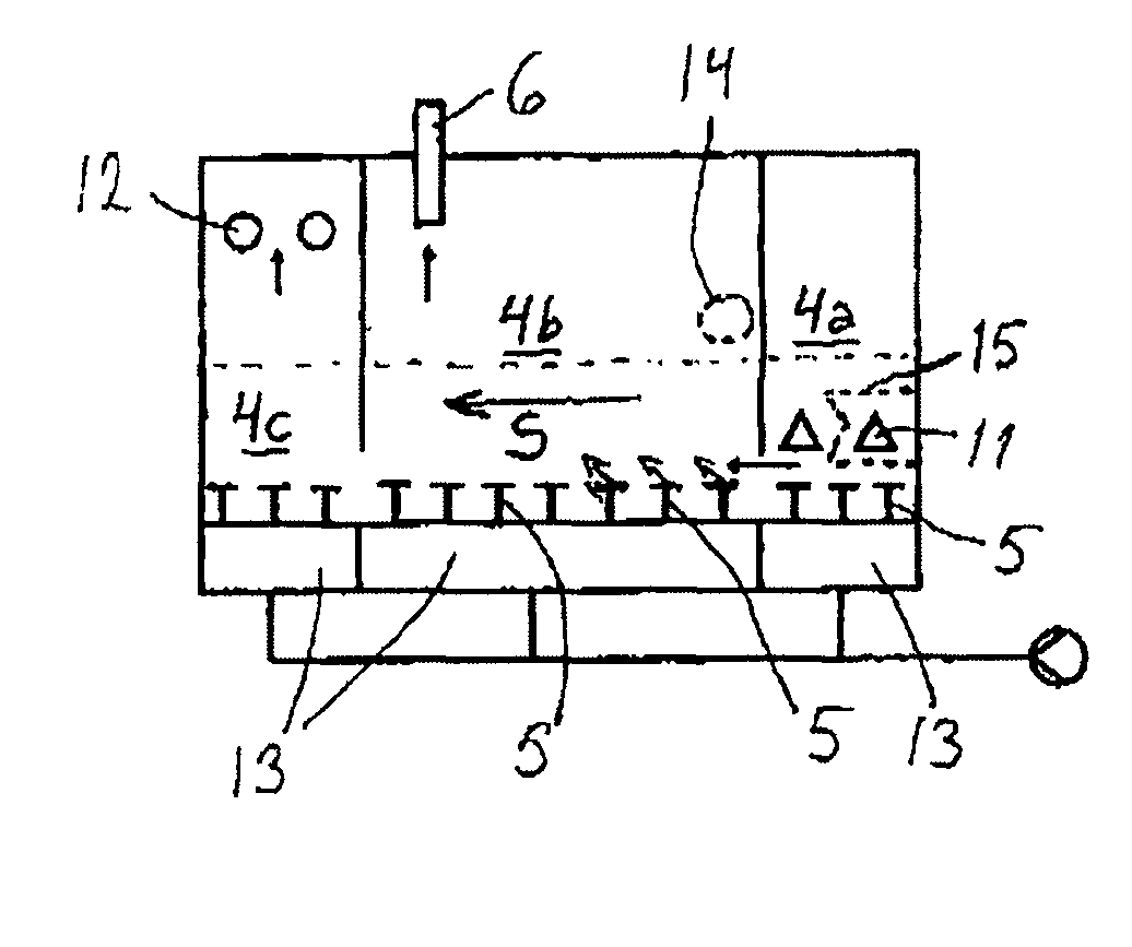
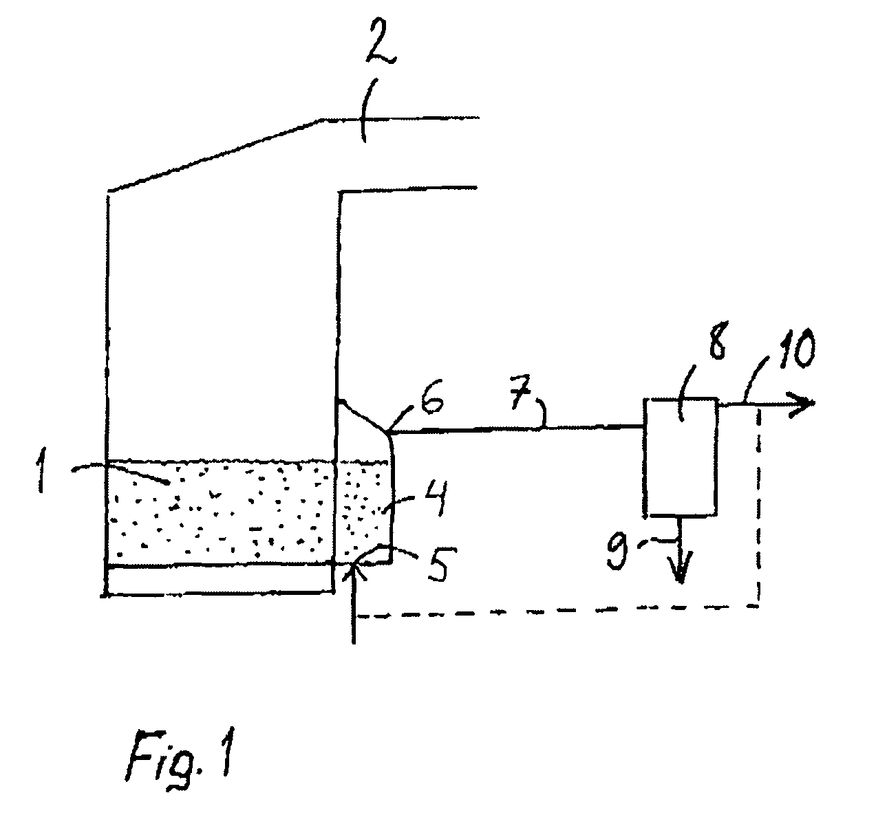
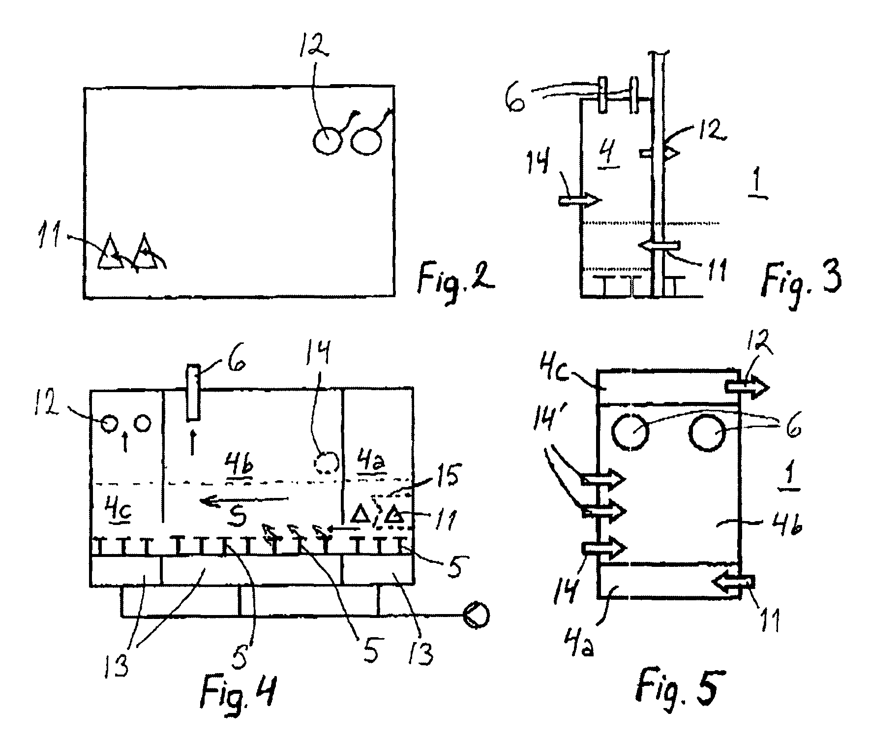
[0018]FIG. 1 schematically shows the process in connection with a combustion boiler. In a combustion boiler the material forms a so-called bubbling fluidized bed (BFB). The boiler comprises a furnace 1 and a flue gas channel 2 exiting the furnace. Fluidized bed material formed of solid particles circulates in the furnace as internal circulation. The fluidized bed material can be, for example, inert material, such as sand. The supply of liquid or solid fuel, fluidizing air and combustion air into the furnace, as well as the elements relating to the generation of steam in the boiler are not presented, as they are irrelevant to the invention.

[0019]In FIG. 1, a pyrolysis process is arranged in connection with a boiler, in which process it is possible to pyrolyze fuel, which may be the same fuel that is supplied to the furnace of the boiler, or a different fuel. The same plant can therefore simultaneously produce energy in the form of steam and / or electricity by combustion process and, b...


PUM

PropertyMeasurementUnit
temperatureaaaaaaaaaa
residence timeaaaaaaaaaa
areaaaaaaaaaaa

Abstract

A pyrolysis apparatus comprises a substantially closed pyrolyzer (4), a supply inlet for supplying pyrolyzable fuel to the pyrolyzer (4), an outlet for taking hot bed material in particle form out of the pyrolyzer, one or more exit outlets (6) for taking condensible gaseous substances separated from the fuel to be pyrolyzed out of the pyrolyzer, a condenser (8) for condensing the condensible gaseous substances into pyrolysis oil, and a line (7) for transferring the condensible gaseous substances from the exit outlet of the pyrolyzer (4) to the condenser (8). The means for maintaining pyrolysis conditions in the pyrolyzer (4) comprise an inlet for taking hot bed material in particle form into the pyrolyzer and means (5) for supplying fluidizing gas to the pyrolyzer.
The pyrolyzer (4) is a chamber bounded directly by a furnace (1) of a bubbling fluidized bed boiler, through which chamber fluidized bed material is arranged to be circulated between the inlet and the outlet. Means (5) for supplying fluidizing gas are divided over an area between the inlet (11) and the outlet (12) in the pyrolyzer (4) so that they create a cross-flow of fluidizing gas in relation to the transfer direction (S) of the bed material and fuel.

Description

BACKGROUND OF THE INVENTION[0001]1. Field of the Invention[0002]The invention relates to a method for performing pyrolysis, which is of the type presented in the preamble of the appended claim 1. The invention further relates to pyrolysis apparatus according to the preamble of the appended claim 8.[0003]2. Description of Related Art[0004]Pyrolysis refers to conversion of fuel in inert conditions and high temperature into gaseous form, which during condensation forms oily liquid that comprises different organic compounds. Inert conditions in connection with pyrolysis refer to oxygen-free conditions, wherein combustion of fuel is avoided. Tar distillation is one example of a pyrolysis process known for ages.[0005]In a pyrolysis process fuel is pyrolyzed, the gaseous compounds formed in the reaction are separated from carbonization residue, and they are condensed into pyrolysis oil, which may be used, for exarnple, as fuel or it may be processed further into different chemicals. Produc...

Claims


Application Information

Patent Timeline
Patent Type & Authority Patents(United States)
IPC IPC(8): C10B49/22C10J1/207
CPCC10B49/22F22B31/0007F23C10/04F23C10/005Y02E50/14F23C2206/102Y02E50/10B01J8/36C10J1/207
Inventor LEHTO, JANI
Owner METSO POWER OY
Why Eureka
Try Eureka