Relay with stair-structured pole faces

a technology of stair-structured pole faces and relays, applied in the direction of magnets, contact mechanisms, magnets, etc., can solve the problems of rf switching noise, loud slapping noise, bounce and chatter, etc., to improve the stroke of armature, improve the structure, and speed up and quiet operation

Active Publication Date: 2013-08-06
INT CONTROL & MEASUREMENTS
View PDF16 Cites 16 Cited by
  • Summary
  • Abstract
  • Description
  • Claims
  • Application Information

AI Technical Summary

Benefits of technology

[0009]It is a more particular object to provide an improved structure for a relay to achieve faster and quieter operation, and improved dynamics of the stroke of the armature, while employing bobbin, coil, spring, yoke and contacts that are the same or similar to those used in similar existing relays.
[0010]It is another object to provide a relay with improved geometry of the core pole face and the mating pole face of the armature to manage the magnetic flux so that initial magnetic force is increased over the conventional design at the commencement of actuation, and is reduced in respect to that of relays of conventional design at closure, so as to avoid acoustical noise, bounce, chatter, and electrical switching noise.
[0011]According to an aspect of this invention, an electromechanical relay is formed of a yoke of a ferromagnetic material, with a relay coil mounted on the yoke, and with the ferromagnetic core being affixed onto the yoke. The core protrudes through an axis of the relay coil. An armature formed of a ferromagnetic material has an armature bearing at a proximal end hinged onto the yoke. The armature extends across the axis of the core. The armature is arranged so that it is pulled in to a closed position against the core when the coil is energized. A return spring is mounted on the yoke and on the armature, and biases the armature so as to pull it to an open position when the coil is de-energized. A movable contact is mechanically carried on the armature to move between open and closed positions. A fixed contact positioned to close electrically with the movable contact when the latter is in one of its open and closed positions. The relay of this invention is improved in that the core pole face, at an axial end of the magnetic core, takes the form of a series of stepped substantially flat strips that extend generally in respective planes and successive ones of which are joined by riser surfaces that extend u

Problems solved by technology

However, due to the fact that the magnetic flux has to move across a gap that diminishes as the armature closes, the armature of the relay experiences a maximum force and acceleration at closure, which can result in a loud slapping noise, and can also produce bounce and chatter at the normally-open (NO) contact.
The bounce or chatter may also produce RF switching noise, which may disturb electronic devices located near the relay.
This results in a large acceleration just as the armature reaches the pole face of the core.
The sudden collision of the armature with the core can cause the armature to bounce off, and can also cause the

Method used


Image

  • Relay with stair-structured pole faces
  • Relay with stair-structured pole faces
  • Relay with stair-structured pole faces

Examples


Embodiment Construction

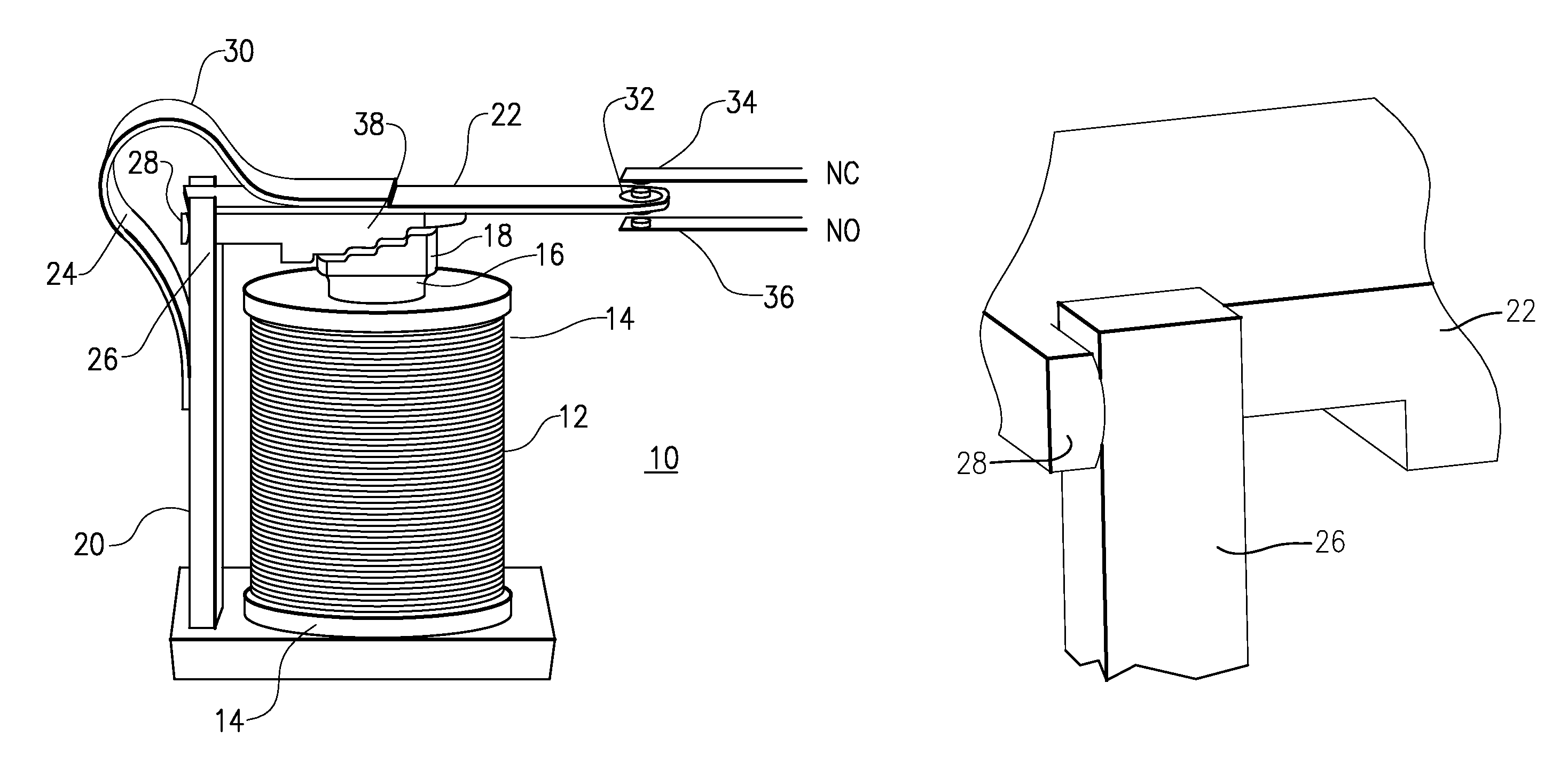
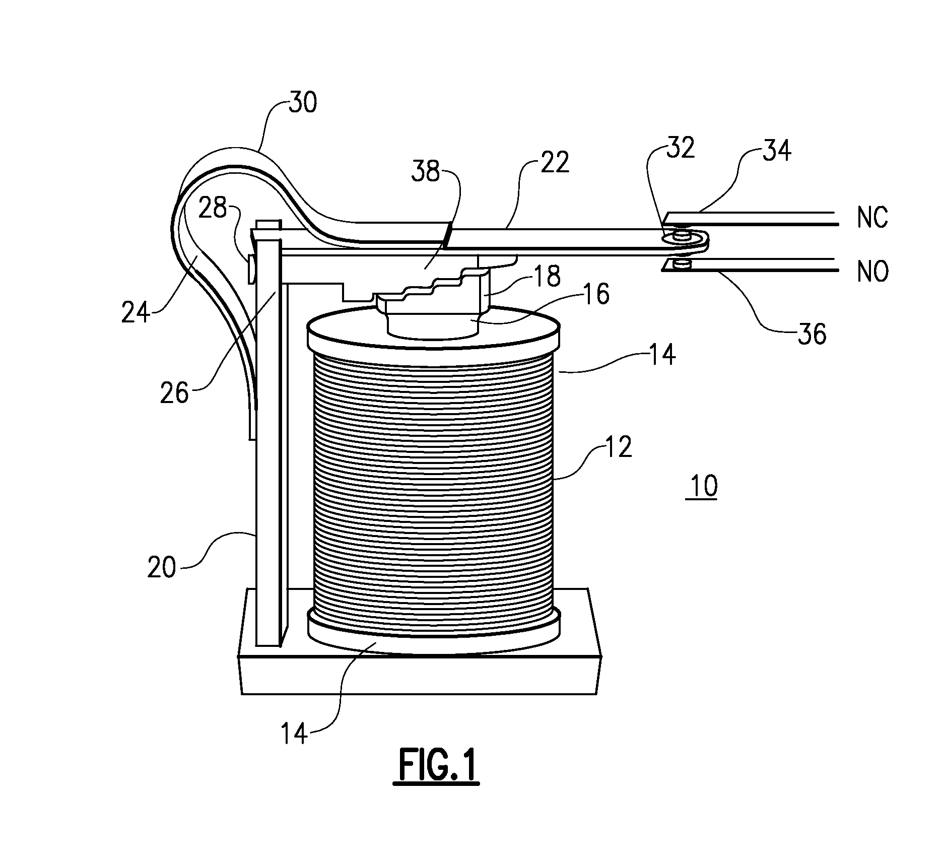
[0030]With reference to the Drawing, and initially to FIG. 1 thereof, a single-pole double-throw relay 10 here is shown to have a relay coil 12 wound on a bobbin 14 with a ferromagnetic core 16, i.e., an iron rod, at the axis of the bobbin. One end of the core protrudes through the coil 10, and is formed as a core pole face 18. A frame or yoke 20, also formed of a ferromagnetic metal, serves as a mount onto which the other end of the core 16 is secured. The yoke also extends parallel to the axis of the coil 12. An armature 22, i.e., a hinged ferromagnetic plate, is mounted at an upper end of the yoke 20 and an armature bearing 24 or hinge is formed there, defining a proximal end of the armature 22. The armature bearing is formed of a pair of posts 26 that extend in the axial direction at the upper end of the yoke 20, and a pair of transverse hinge members 28 or arms formed on the proximal end of the armature 22. These hinge members 28 have arcuate, i.e., radiused faces that contact ...


PUM


Abstract

In an electromechanical relay the core of the relay coil and a corresponding zone of the armature are each provided with a pole face of zig-zag or stair-step configuration. A succession of corresponding edges of the core and armature pole faces concentrate the magnetic flux to increase the initial force on the armature and to limit the closing force as the armature reaches the closed position. The armature bearing is shaped to create a longitudinal wipe motion. The relay exhibits faster and quieter action with less bounce and reduced contact chatter.

Description

BACKGROUND OF THE INVENTION[0001]This invention relates to electromagnetic relays and contactors, and is more specifically related to the structure of an electromagnetic or electromechanical relay of the type that has a winding or coil that is energized to move an armature such that a load current may be applied to a load device. Relays and contactors may be considered as devices in which the appearance of a pilot current or voltage causes the opening or closing of a controlled switching device to apply or discontinue application of load current. The invention is particularly concerned with a the structure of the magnetic pole piece of the magnetic core of the winding, and the corresponding pole piece of the movable armature, structured in a way that manages the magnetic flux between core and armature as the armature closes so as to avoid noise, chatter, and wear, and to permit the relay to operate at smaller values of current for a given coil.[0002]Electromagnetic or electromechani...

Claims


Application Information

Patent Timeline
IPC IPC(8): H01H51/22H01H3/60
CPCH01H3/60H01H50/16H01F7/14H01F7/081H01F2007/086
Inventor AHMAD, AYHAMKADAH, HASSAN B.KADAH, ANDREW S.
Owner INT CONTROL & MEASUREMENTS
Why Eureka
Try Eureka