Self-luminescent display device having a temperature and light sensor for correcting image data and electronic apparatus thereof

a self-luminescent display and temperature sensor technology, applied in the direction of electroluminescent light sources, static indicating devices, instruments, etc., can solve the problems of increasing power consumption, accelerating degradation of pixels, and difficulty in most suitably correcting images, etc., to achieve constant image display, small size, and high quality

Active Publication Date: 2013-08-13
SEIKO EPSON CORP
View PDF11 Cites 33 Cited by
  • Summary
  • Abstract
  • Description
  • Claims
  • Application Information

AI Technical Summary

Benefits of technology

[0011]For instance, the image correcting unit analyzes a brightness histogram of the input image data and corrects the image data in such a way, if it is identified that the light emitting brightness of the whole screen is high like an all-white image, as to shift the brightness histogram (brightness distribution) to a low brightness side. Thus, e.g., even if a highly bright image close to an all-white image is displayed for a long time, degradation of pixels is prevented and something like screen burn-in less probably occurs. Further, as driving currents of individual pixels are suppressed, effects of reducing power consumption in the pixel unit and of a longer lifetime of a display panel are obtained. Further, the display control unit produces a brightness correcting signal on the basis of a light adjusting signal produced on the basis of an external light intensity and a temperature correcting signal produced on the basis of a temperature. Light emitting brightness of the pixels is adjusted by means of the brightness correcting signal. For instance, a brightness correction is made such that the light emitting brightness of the pixels in case of intense external light (the surrounding are light) is rendered high as the screen becomes hard to see in such a case, and that the light emitting brightness of the pixels in case of weak external light (the surrounding are dark) is rendered lower than that in the light surroundings case. Further, if brightness of an organic EL element rises almost in proportion to the temperature, a brightness correction is made by means of an opposite correction characteristic to the brightness change of the organic EL element (as to the above example, a characteristic such that the brightness almost linearly falls as the temperature rises) so as to suppress the rise of the brightness.
[0034]The electronic apparatus equipped with the self-luminescent display device of the invention enjoys a benefit of a constant image display of high quality, small size and low power consumption.

Problems solved by technology

As an external light intensity and a temperature suddenly change in accordance with surrounding conditions in some cases, it is difficult to most suitably correct an image on, e.g., a display panel to be mounted on a mobile electronic device only by means of light emitting brightness control based on either one of the external light and the temperature.
Further, in a case where a display device using a self-luminescent element such as an organic EL element displays a highly bright image such as an all white image (i.e., most of pixels of a screen emit highly bright light), degradation of the pixels is accelerated resulting in a change of image quality and an increase of power consumption.
Further, if a portion of a pixel unit regularly emits light for a long time and a display of same image data continues in the portion for a long time, characteristics of pixels are severely degraded in the portion, screen burn-in occurs and a brightness difference between the portion and a surrounding area increases resulting in brightness unevenness in some cases.
Thus, if the vehicle travels for a long time, characteristics of the organic EL elements of the portion which indicates the outer fringes, gauges and numerals of the meters severely change (they are severely degraded), possibly resulting in screen burn-in.
If the displayed image changes from the image of the meters to a navigation or TV image after the screen burn-in occurs, brightness in the portion where the screen burn-in has been caused by the display of the meters may possibly change from a precise value beyond an allowable range, and may possibly degrade quality of the navigation or TV image which should primarily be highly precise.
Ordinary image correction technologies cannot optimize light emitting brightness in such a way, e.g., as to properly deal with all the above problems.
If the duty ratio of the PWM signal becomes, e.g., less than 50 percent, a period of time for which the light emitting element is not lit extends and a flicker may possibly occur.
If the displayed image changes from the image of the meters to a navigation or TV image after the screen burn-in occurs, brightness in the portion where the screen burn-in has been caused by the display of the meters may possibly change from a precise value beyond an allowable range, and may possibly degrade quality of the navigation or TV image which should primarily be highly precise.
Thus, if a significant change of the brightness characteristic that occurred in some area before the changeover of the image affects the image after the changeover, an unnatural change of the image quality occurs in the image after the changeover.
Further, degradation of characteristics of pixels may be accelerated by self-heat generation caused by long time light emission in some cases.

Method used


Image

  • Self-luminescent display device having a temperature and light sensor for correcting image data and electronic apparatus thereof
  • Self-luminescent display device having a temperature and light sensor for correcting image data and electronic apparatus thereof
  • Self-luminescent display device having a temperature and light sensor for correcting image data and electronic apparatus thereof

Examples


first embodiment

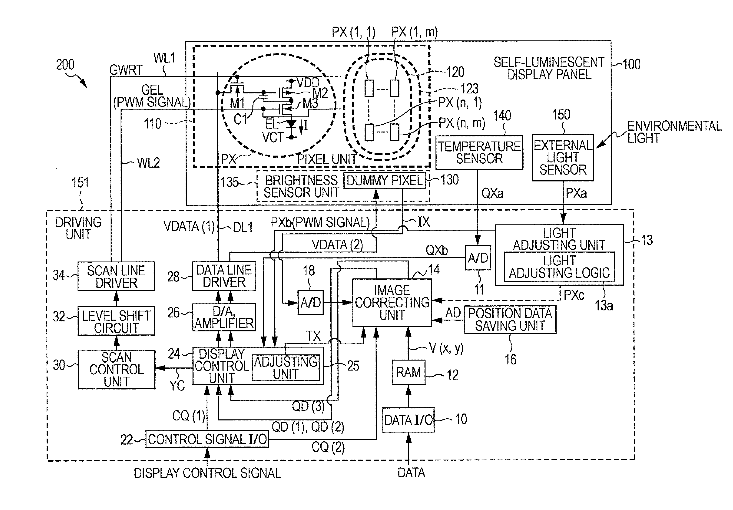
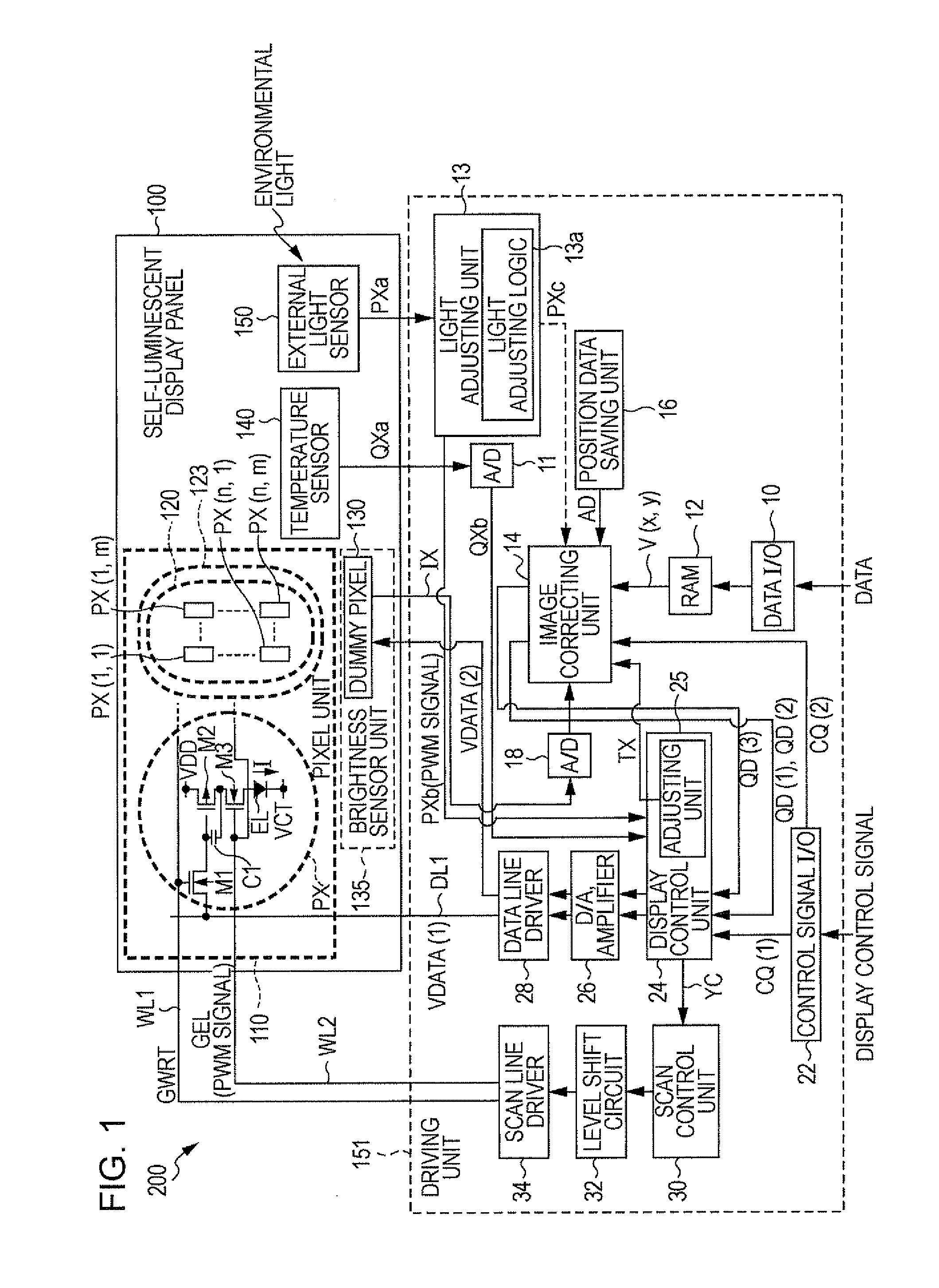
[0048]FIG. 1 shows an example of a configuration of a self-luminescent display device of the invention. A self-luminescent display device 200 has a self-luminescent display panel 100 using organic EL elements and a driving unit 151 of the self-luminescent display panel.

Configuration of Self-Luminescent Display Panel

[0049]The self-luminescent display panel 100 has a pixel unit 110 in which a plurality of pixels PX are arranged in a matrix and a brightness sensor unit 135 including a dummy pixel 130.

[0050]Each of the pixels PX is provided to a crossing of each of a plurality of scan lines (to put it specifically, a first scan line WL1) and each of a plurality of data lines (DL1). The pixel PX includes a writing transistor M1, a driving transistor M2, a light emitting control transistor M3, a holding capacitor C1 and an organic EL element EL. The driving transistor M2 has a source connected to a pixel power supply voltage VDD of a high level. The organic EL element EL has a cathode con...

second embodiment

[0079]According to the embodiment, the self-luminescent device controls a compensation for secular degradation on the basis of the detection signal IX of the brightness sensor unit 135 in addition to the three kinds of light emitting brightness correction (image correction based on statistical data of input image data, brightness correction based on external light and temperature) described above. That is, focus on a portion in which secular degradation is expected to be severe and intensively correct brightness in an area close to an interface between that portion and the surroundings, so that size of pixels to be corrected can be made small and the load of the correcting circuit can be reduced. Brightness unevenness can be efficiently and effectively prevented from occurring, e.g., in an area in which a same image is displayed for a long time and in the surrounding area by means of the compensation for secular degradation. According to the embodiment, four kinds of light emitting ...


PUM


Abstract

A self-luminescent display device includes a pixel unit in which a plurality of pixels including a self-luminescent pixel is arranged, an external light sensor which measures an external light intensity, a temperature sensor which measures an environmental temperature, an image correcting unit which corrects image data input to the image correcting unit on the basis of statistical data of the image data, a light adjusting unit which produces a light adjusting signal on the basis of a measurement signal of the external light sensor, a temperature control unit which produces a temperature correcting signal on the basis of a measurement signal of the temperature sensor, and a display control unit which produces a brightness correcting signal for correcting light emitting brightness of the pixels in the pixel unit on the basis of the light adjusting signal and the temperature correcting signal. The light emitting brightness of the pixels in the pixel unit is adjusted on the basis of the image data corrected by the image correcting unit and the brightness correcting signal.

Description

BACKGROUND[0001]1. Technical Field[0002]The present invention relates to a self-luminescent device and an electronic apparatus.[0003]2. Related Art[0004]Light emitting efficiency of an organic EL element that is a self-luminescent element changes depending upon temperature. Thus, light emitting brightness changes depending upon a change of environmental temperature, a change of panel temperature caused by self-heat generation and so on. In order to deal with such changes, a technology for correcting a light emitting intensity of pixels including light emitting elements on the basis of an output of a temperature sensor is disclosed, e.g., in JP-A-2007-240812. Further, easiness to see of a screen also changes depending upon external light intensity. In order to deal with such a change, a technology for correcting a light emitting intensity of pixels including light emitting elements on the basis of an external light intensity is disclosed, e.g., in JP-A-2005-19353.[0005]As an external...

Claims


Application Information

Patent Timeline
Patent Type & Authority Patents(United States)
IPC IPC(8): G09G3/30H05B44/00
CPCG09G3/3233G09G2320/0285G09G2320/029G09G2320/041G09G2320/043G09G2320/0626G09G2360/144G09G2360/16
Inventor KIMURA, FUSASHITSUDA, ATSUNARI
Owner SEIKO EPSON CORP
Why Eureka
Try Eureka