

Image bearing member to which boron nitride is attached
a bearing member and boron nitride technology, applied in the field of image bearing members, can solve the problems of heavy mechanical stress, shorten the working life of both the cleaning blade and the organic photoconductor, and achieve the effect of less frequent replacemen
- Summary
- Abstract
- Description
- Claims
- Application Information
AI Technical Summary
Benefits of technology
Problems solved by technology
Method used
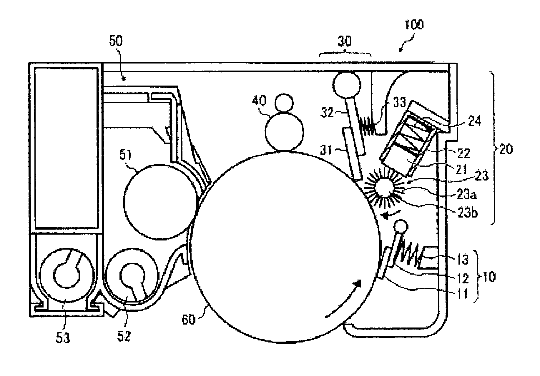
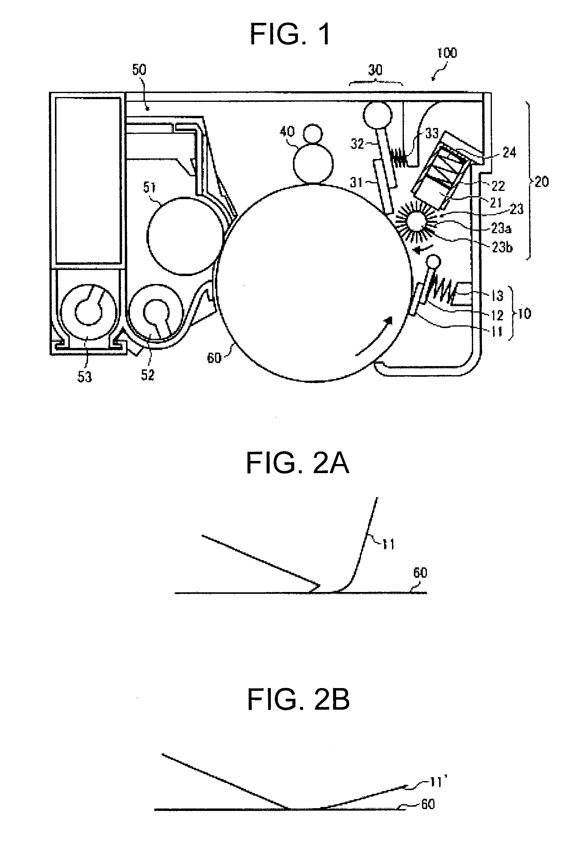
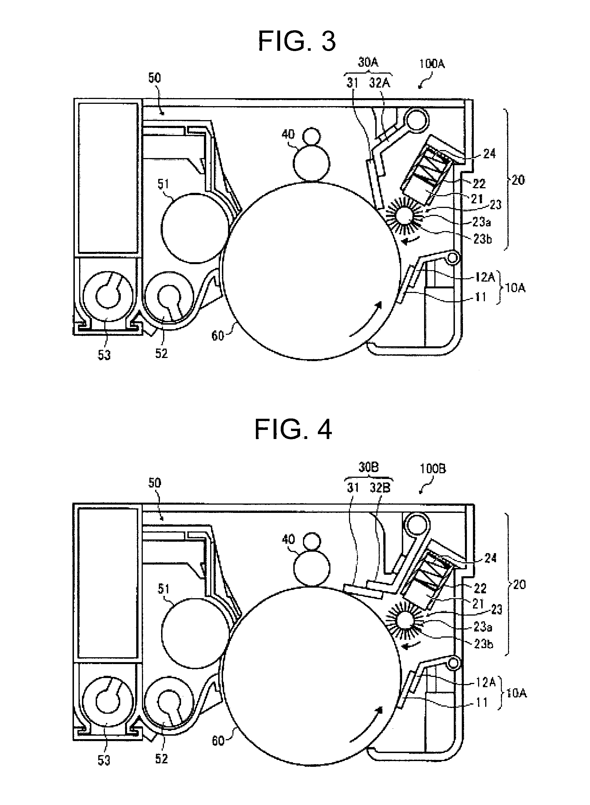
Image

Examples
manufacturing example 1
Manufacturing of Protective Agent Bar 1
[0818]A powder mixture of zinc stearate and zinc palmitate, both of which have an average particle diameter of 17 μm is placed in an aluminum mold having an inner size of 8 mm×350 mm, and compressed by using a hydraulic press until the mixture is compressed to 95% of the true specific gravity to obtain a bar having a thickness of 7 mm.
[0819]The both ends of the manufactured bar in the longitudinal direction are severed and the bottom face is cut to obtain [Protective agent bar 1] having a dimension of 7 mm×8 mm×310 mm. Double-faced adhesive tape is attached to the bottom of manufactured [Protective agent bar 1] to fix it to a metal support.
manufacturing example 2
Manufacturing of Protective Agent Bar 2
[0820]Boron nitride (BN, having an average particle diameter of 5 μm) is mixed and stirred with a mixture of zinc stearate and zinc palmitate, both of which have an average particle diameter of 17 μm such that the content of boron nitride is an amount of 3% by weight. The powder obtained after stirring is placed into an aluminum die having an inside dimension of 8 mm×350 mm and pressed by a hydraulic pressing machine to 95% of the true specific gravity to manufacture a protective agent bar having a thickness of 7 mm. The both ends of the manufactured bar in the longitudinal direction are severed and the bottom face is cut to obtain [Protective agent bar 2] having a dimension of 7 mm×8 mm×310 mm.
[0821]Double-faced adhesive tape is attached to the bottom of manufactured [Protective agent bar 2] to fix it to a metal support.
manufacturing example 3
Manufacturing of Protective Agent Bar 3
[0822]Boron nitride (BN, having an average particle diameter of 5 μm) is mixed and stirred with a mixture of zinc stearate and zinc palmitate, both of which have an average particle diameter of 17 μm such that the content of boron nitride is an amount of 30% by weight. The powder obtained after stirring is placed into an aluminum die having an inside dimension of 8 mm×350 mm and pressed by a hydraulic pressing machine to 95% of the true specific gravity to manufacture a protective agent bar having a thickness of 7 mm. The both ends of the manufactured bar in the longitudinal direction are severed and the bottom face is cut to obtain [Protective agent bar 3] having a dimension of 7 mm×8 mm×310 mm. Double-faced adhesive tape is attached to the bottom of manufactured [Protective agent bar 3] to fix it to a metal support.
PUM
| Property | Measurement | Unit |
|---|---|---|
| particle size | aaaaa | aaaaa |
| particle size | aaaaa | aaaaa |
| diameter | aaaaa | aaaaa |
Abstract
Description
Claims
Application Information