Optical fiber network test method of an optical frequency domain reflectometer

a technology of optical fiber network and optical frequency domain, which is applied in the direction of optical transmission, electromagnetic transmission, instruments, etc., can solve the problems of large effectiveness flaw, difficult questioning of optical fiber test/monitoring, and inability to afford high-speed information transmission on the traditional network, so as to achieve the effect of reducing the cost of maintenance sand operation

Inactive Publication Date: 2013-08-20
CHUNGHWA TELECOM CO LTD
View PDF3 Cites 13 Cited by
  • Summary
  • Abstract
  • Description
  • Claims
  • Application Information

AI Technical Summary

Benefits of technology

[0007]The present invention is an optical fiber network test method of an optical frequency domain reflectometer. When the service system has problem, it is possible to test / monitor whether the optical fiber is disconnected, optical reflection or too much optical loss vale in a generation room. To clarify where the question is: is it on service system, optical router or connector? Show the right positions of optical fiber barrier and connector to lower the cost of maintenance sand operation.
[0008]To Achieve the above mentioned invention of the optical fiber network test method of the optical frequency domain reflectometer, which is to use a optical fiber test and measure apparatus to test / monitor the quantity of optical power reflected by the optical fiber and is the way to measure the distance of I-OFMCW (Incoherent-Optical Frequency-Modulated Continuous-Wave). Thus, we can simultaneously confirm the positions of optical events such as barrier router and connector. The method is to use the test distance of testing or monitoring the quantity of optical power reflected by the optical fiber and is the way to measure the distance of I-OFMCW (Incoherent-Optical Frequency-Modulated Continuous-Wave), analyze these data gradually to determine the latest status of the optical fiber. When it occurs barrier events such disconnection or deterioration on optical fiber or connector, the present invention can quickly analyzes a solution and provides a basis for the following alert and handling.
[0009]The present invention is an optical fiber network test method of an optical frequency domain reflectometer, which possesses the following advantages comparing to the other conventional inventions:
[0010]1. The present invent may test / monitor the optical fiber in a generation room through the reflection of the router's end (optical fiber's cross-section or optical fiber's connector opening) or equip a wave reflector monitor, such provides a feasible, reliable and effective test / monitor method of the optical fiber.
[0013]4. The present invention provides an single-ending and long-term automatically optical fiber network test / monitor, which the present invention provides a better service quality through quickly and correctly clarifying the barrier events on service system or optical fiber router, and processing the preventive maintenance for the latest status.
[0014]5. The present invention may not only lower the network maintenance cost of human affairs, but also ensure the reliability and stability of optical fiber network, thus upgrade the maintenance efficiency. The economic benefit is very obvious.

Problems solved by technology

With the rapid global internet growing, the traditional network could not afford the need of high-speed information transmission due to the communication revolution.
Processing the test / monitor of the optical fiber has been a difficult question due to the framework design of the optical fiber.
There was a monitor method which is using Optical Time Domain Reflectometer (OTDR), but such test method takes a lot of time, therefore it becomes a huge flaw on effectiveness.
It is obvious that there are still many flaws on the conventional invention mentioned above, which is really not designed well and extremely needed to be improved.

Method used


Image

  • Optical fiber network test method of an optical frequency domain reflectometer
  • Optical fiber network test method of an optical frequency domain reflectometer
  • Optical fiber network test method of an optical frequency domain reflectometer

Examples


Embodiment Construction

[0020]The present invention is an optical fiber network test method of an optical frequency domain reflectometer.

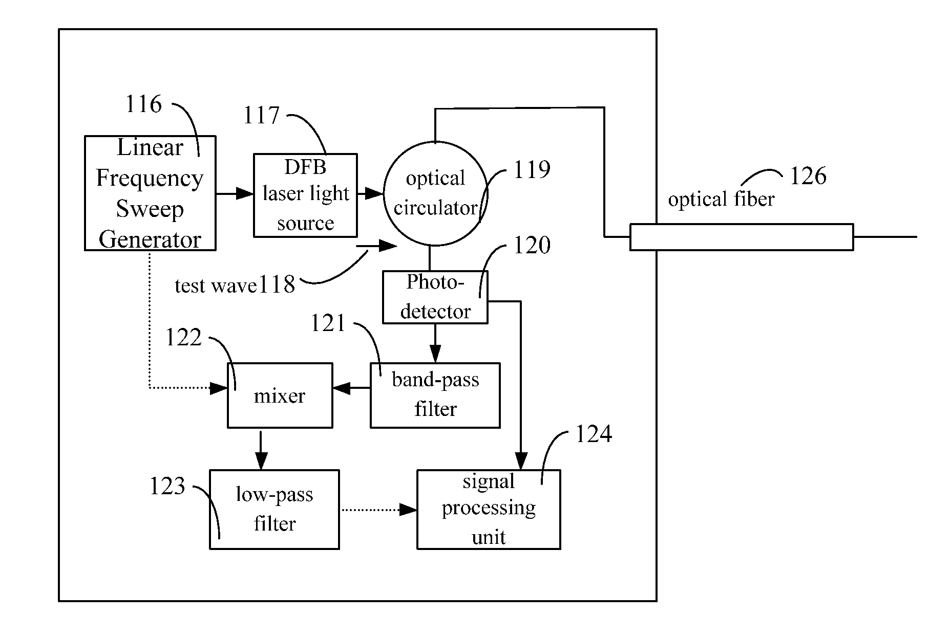
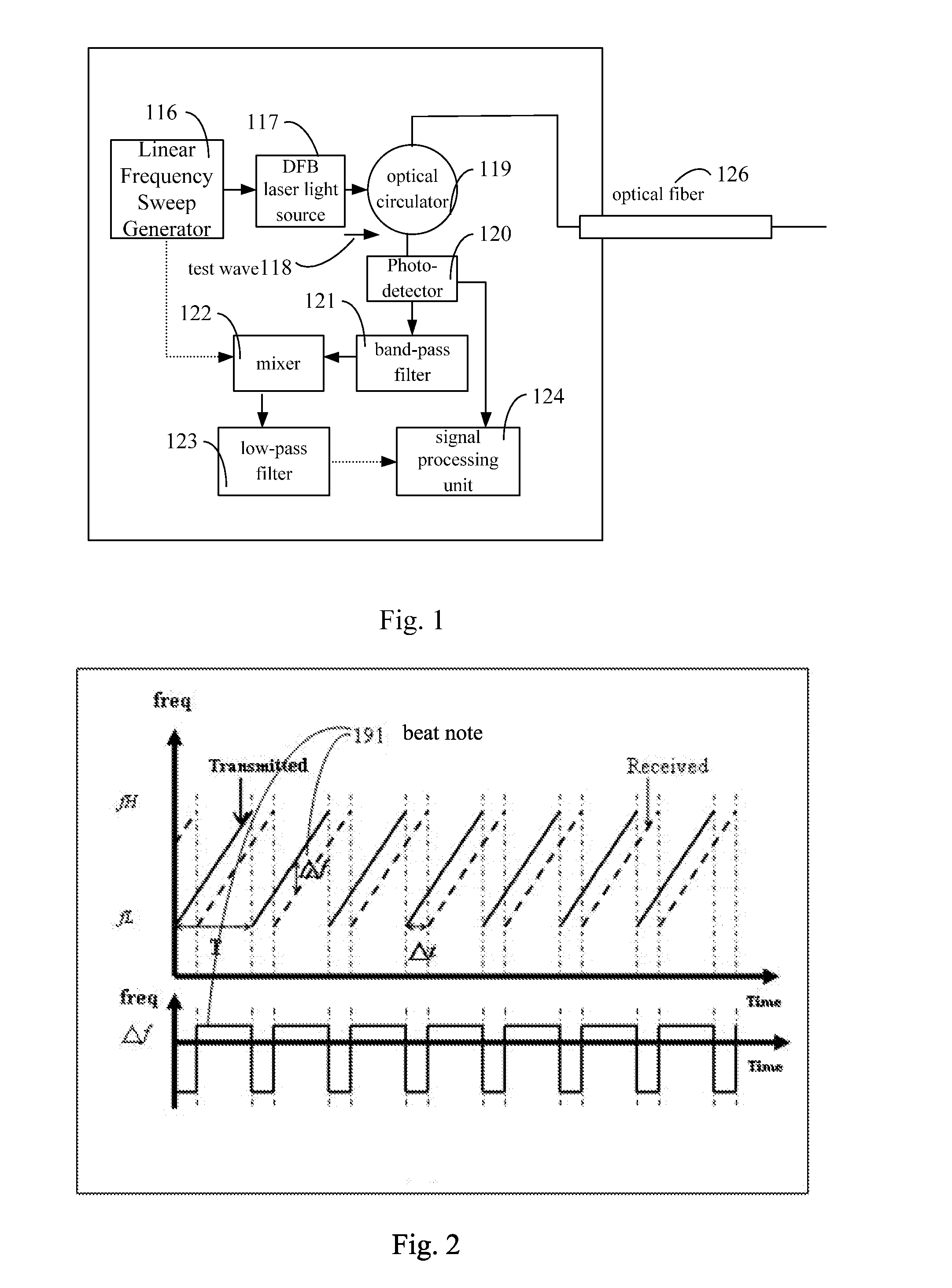
[0021]Please refer to the FIGS. 1 and 2. FIG. 1 is an architecture diagram of the optical fiber network monitor or test method of an optical frequency domain reflectometer of the present invention; FIG. 2 is a schematic diagram, in which the operation principle of FMCW show the beat notes produced from the different distances. As the FIG. 1 shows, the test / monitor method processing is as follows: a linear frequency scanning signal producer 116 modulates a DFB laser light source 117 and the optical signal of monitoring wave 118 is adapted to be transmitted through an optical circulator 119, and the optical signal is adapted to be transmitted to the end of the optical cable routing through an optical cable 126. After being reflected by the optical fiber's cross-section, the monitoring wave is adapted to turn back along the original route, pass through the optical cable 126 ...


PUM

PropertyMeasurementUnit
optical fiber network testaaaaaaaaaa
opticalaaaaaaaaaa
frequency modulation rateaaaaaaaaaa

Abstract

An optical fiber network test method of an optical frequency domain reflectometer, which is to use the optical testing apparatus and method of the prevent invention to combine the characters of filtering, reflecting and transmission of light of the wave reflecting unit, applying on any optical fiber test or point-to-point or point-to-multipoint optical fiber network. Thus, the optical fiber testing apprartus and method is constructed, and the goals of achieving the optical fiber network test method of the optical frequency domain reflectometer or confirming simultaneously the position of the barrier router and the barrier optical fiber connection point / end point / start point can be accomplished.

Description

BACKGROUND OF THE INVENTION[0001]1. Field of the Invention[0002]The present invention is an optical fiber network test method of an optical frequency domain reflectometer, which is easy to use with high efficiency and applied on any optical fiber test method of the optical frequency domain reflectometer or any optical fiber test or point-to-point or point-to-multipoint passive optical network.[0003]2. Description of the Prior Art[0004]With the rapid global internet growing, the traditional network could not afford the need of high-speed information transmission due to the communication revolution. The industrial technology maturation and diversified application products of optical-electro products timely supply the best solution for the huge bandwidths requirement of rapidly-growing global internet, high-quality multimedia networks, and a variety of data communications. Therefore, many types of optical communication network forums appear one after another, wherein the optical fiber ...

Claims


Application Information

Patent Timeline
Patent Type & Authority Patents(United States)
IPC IPC(8): G01N21/00
CPCH04B10/071H04B2210/07
Inventor SHAO, SHOU-KUOWANG, CHIH-YIHHSU, YU-JENWU, CHIA-HSIENTSAI, FWU-YUAN
Owner CHUNGHWA TELECOM CO LTD
Why Eureka
Try Eureka