
Multiple transition RNP approach procedure

a multi-transition, approach procedure technology, applied in the direction of navigation instruments, instruments, process and machine control, etc., can solve the problems of not being able to accept rnp procedures at high-congestion airports, pilots cannot operate aircraft nearly as efficiently, and unable to achieve rnp procedures acceptance at high-congestion airports, so as to reduce workload

Active Publication Date: 2013-08-20
THE BOEING CO
View PDF16 Cites 3 Cited by
  • Summary
  • Abstract
  • Description
  • Claims
  • Application Information

AI Technical Summary

Benefits of technology

This patent describes a method for allowing aircraft to safely approach an airport and land without needing assistance from a controller. The method involves providing multiple fixed points along the approach route and connecting them with constant radius turnpoints. This approach allows the aircraft to fit in with the traffic pattern at the airport, making it easier for controllers to manage and compatible with other traffic. The method also results in more efficient and predictable flight paths for aircraft flying the approach, leading to better performance and more widespread acceptance of the approach.

Problems solved by technology

For example, by merely applying the same approach, speed, and decent rate to every given aircraft, which is one current non-RNP approach, a pilot cannot operate an aircraft nearly as efficiently.
Nevertheless, acceptance of RNP procedures is not being achieved at high congestion airports, because air traffic controllers (ATCs) cannot easily combine airplanes flying customized RNP approaches with air traffic unable to conduct a RNP approach.
Since the ATCs primary concern is keeping two aircraft from being in the same location at the same time rather than the efficiency of the approach for any particular aircraft, the RNP procedures are not being accepted.
As a result, many aircraft are not operating with peak efficiency due to constraints applied by ATCs.
While known RNP procedures could provide improved efficiency for aircraft capable of flying RNP approaches, they are not used by ATC since a faster aircraft could potentially overtake a slower aircraft flying in the same traffic pattern.
Thus, current RNP approaches do not integrate well with the type of traffic patterns and separation requirements that local ATCs prefer, and the potential savings in fuel, operations and emissions are therefore not realized.

Method used


Image

  • Multiple transition RNP approach procedure
  • Multiple transition RNP approach procedure
  • Multiple transition RNP approach procedure

Examples


Embodiment Construction

[0021]As used herein, an element or step recited in the singular and proceeded with the word “a” or “an” should be understood as not excluding plural said elements or steps, unless such exclusion is explicitly stated. Furthermore, references to “one embodiment” are not intended to be interpreted as excluding the existence of additional embodiments that also incorporate the recited features. Moreover, unless explicitly stated to the contrary, embodiments “comprising” or “having” an element or a plurality of elements having a particular property may include additional such elements not having that property.

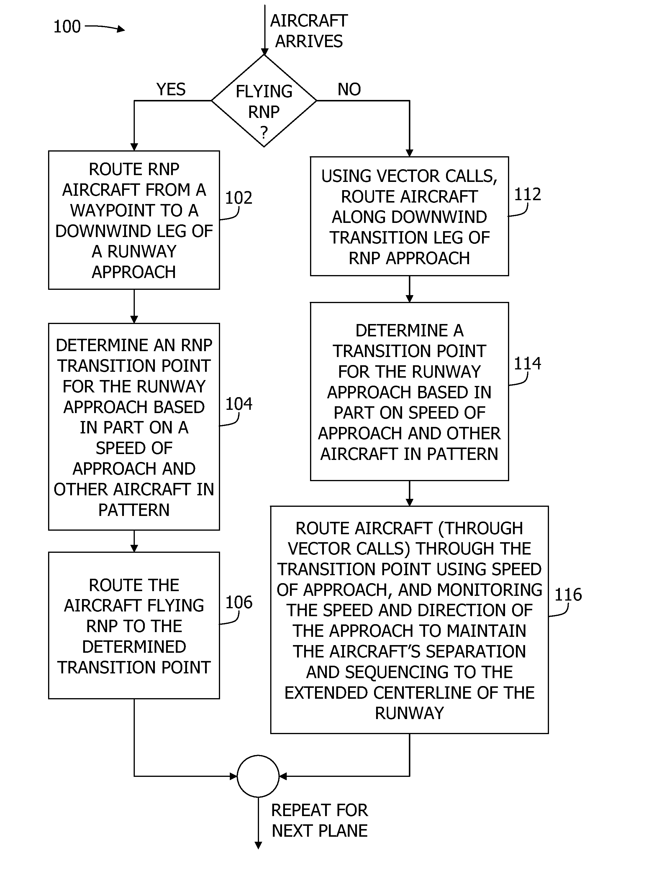
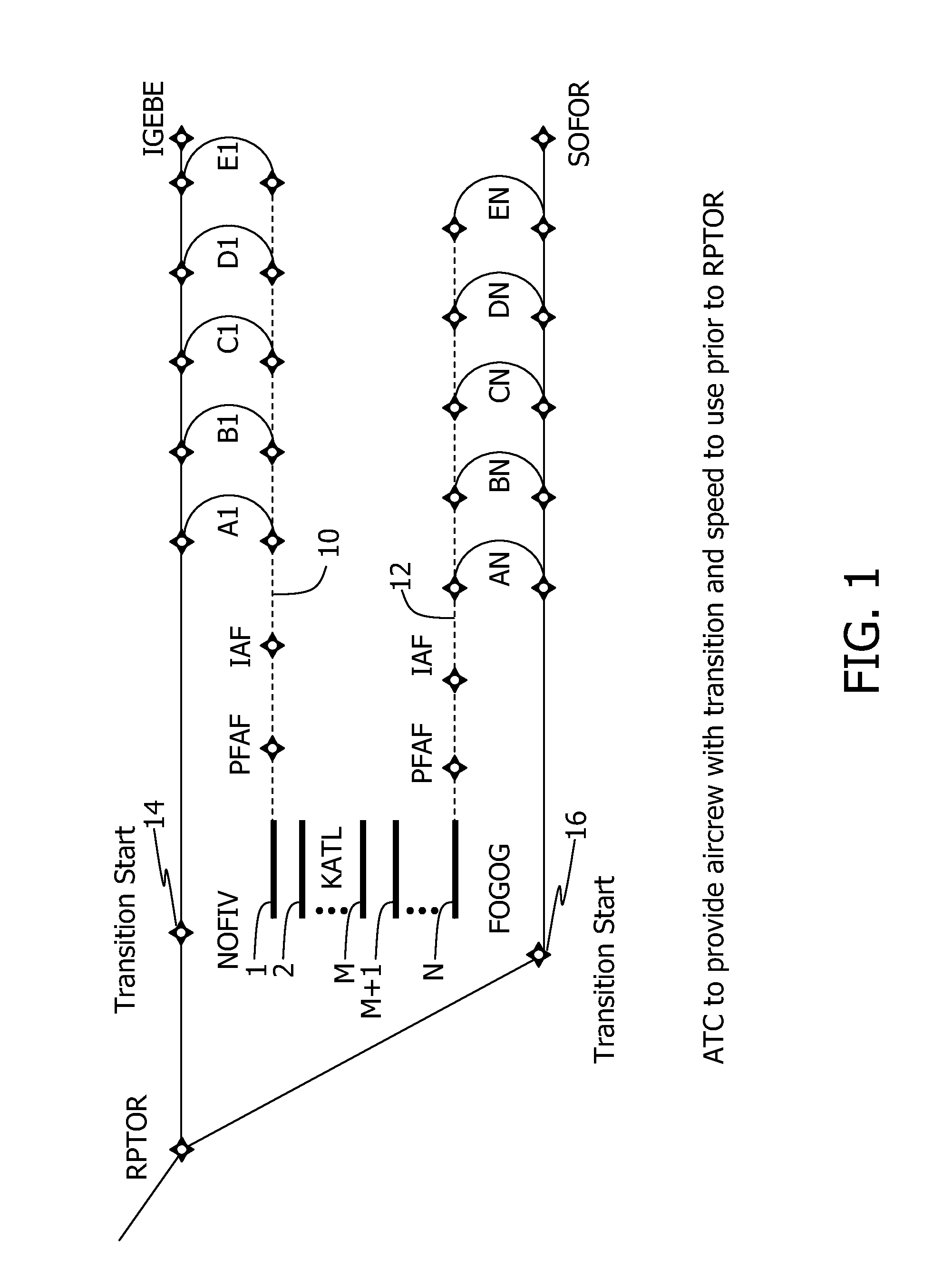
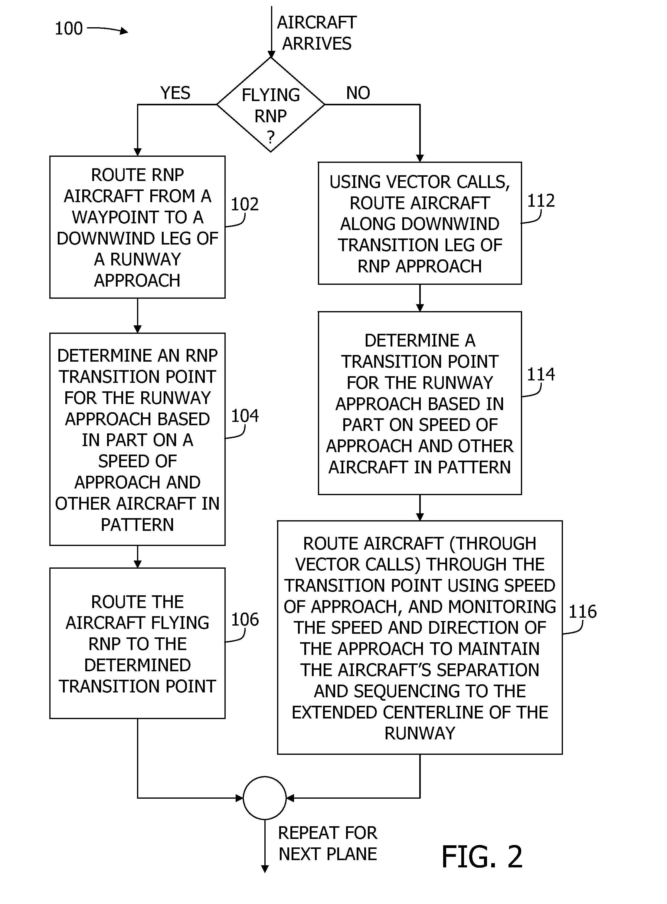
[0022]Some embodiments combine an RNP approach route with a standard two-dimensional horizontal traffic pattern. However, these embodiments also add multiple turn points to an approach pattern which have the effect of maintaining horizontal separation between aircraft in the approach pattern while also enabling RNP benefits for aircraft flying the RNP approach. Aircraft having diffe...


PUM


Abstract

A required navigation performance (RNP) approach method is described that includes providing a plurality of fixed, predetermined waypoints associated with at least one runway of at least one airport, providing a predetermined plurality of constant radius turnpoints connecting a downwind leg of the runway to a final approach leg of the runway, and assigning one of the constant radius turnpoints to an aircraft capable of flying an RNP approach, the turnpoint selected to provide separation from other approaching aircraft and a landing time for the aircraft.

Description

CROSS REFERENCE TO RELATED APPLICATIONS[0001]This application claims the benefit of Provisional Patent Application Ser. No. 61 / 285,453, filed Dec. 10, 2009 and Provisional Patent Application Ser. No. 61 / 285,831, filed Dec. 11, 2009, both of which are hereby incorporated by reference in their entirety.BACKGROUND[0002]This disclosure relates generally to required navigation performance (RNP) procedures, and more particularly to methods, apparatus, and design systems for aircraft traffic control based on required navigation performance standards and metrics.[0003]Performance-based aircraft applications include area navigation (RNAV) and required navigation performance (RNP) systems and metrics. These systems and metrics define certain performance levels, performance, functionality, and capability as agreed-upon standards. The aviation community has been broadly adopting RNAV and RNP. The FAA is implementing RNAV and RNP for operations conducted under instrument flight rules (IFR), but ...

Claims


Application Information

Patent Timeline
Patent Type & Authority Patents(United States)
IPC IPC(8): G01C23/00G01C21/00
CPCG08G5/0043G08G5/025G08G5/0013G08G5/0039Y02T50/80
Inventor MCDOWELL, ANDREWBRUCE, JEFFERY LEON
Owner THE BOEING CO
Learn More