Process for increasing the transport flow rate of oil from producing wells

a technology for transporting flow and oil, which is applied in the direction of fluid removal, pipeline systems, borehole/well accessories, etc., can solve the problems of reducing the efficiency of oilfield operation, limiting the flow rate in the installation, and emulsion settles very quickly, so as to increase the amount of active matter injected and reduce viscosity

Inactive Publication Date: 2013-08-27
S P C M SA
View PDF4 Cites 43 Cited by
  • Summary
  • Abstract
  • Description
  • Claims
  • Application Information

AI Technical Summary

Benefits of technology

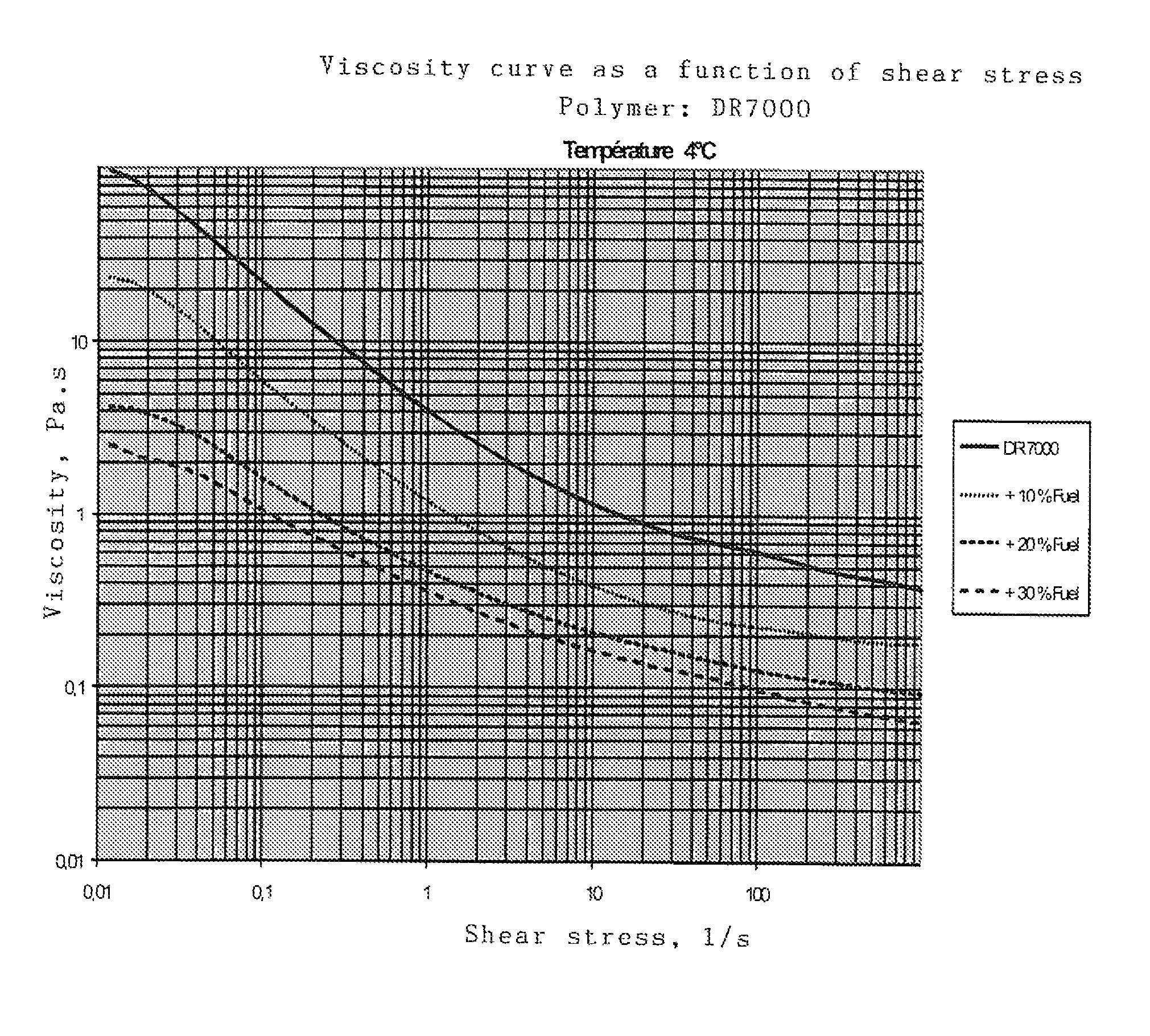
[0020]More particularly, the subject of the invention is a process in which the polymer injected to reduce friction is diluted beforehand with fuel oil, thus reducing the viscosity of the mixture, increasing the rate of injection and, in the end, increasing the amount of active polymer matter injected.
[0024]Thus, by injecting a polymer / fuel mixture, even if the polymer concentration is decreased slightly, the viscosity is decreased enough to significantly increase the amount of active matter injected due to the increase in the rate of injection.
[0044]degassing in a vacuum or by nitrogen injection to eliminate the oxygen;

Problems solved by technology

Obviously, for the same flow rate in the production pipeline, it becomes less profitable to operate the oilfields.
If these installations are already in place, this operation is limited as the materials are calculated for a predetermined friction reduction.
Furthermore, the temperature of seawater (approximately 4° C.) limits the flow rate in the installation.
But in this case, the emulsion settles very quickly and forms viscous layers that solidify on the bottom of the transport containers.
The installations on platforms or FPSOs are not able to re-homogenize it under local operating conditions.
This solution therefore is not practically viable.

Method used


Image

  • Process for increasing the transport flow rate of oil from producing wells

Examples


example 1

[0052]pipe diameter: 1 inch, inside diameter: 25.0 mm. First, the emulsion is pumped “as is” at a speed of 0.063 m / second (or 0.11 m3 / h), which is the average speed for long-distance pumping.

[0053]The pressure drop observed is 2.7 bars / 100 m.

[0054]The emulsions diluted by adding 10% and 20% fuel oil are then pumped, measuring the flow rate with the same pressure drop of 2.7 bars / 100 m. The results are as follows:

[0055]

Active matter perEmulsionFlow ratePressure drophourUndiluted0.11 m3 / h2.7 bars 33 kg10% diluted0.37 m3 / h2.7 bars100 kg20% diluted0.78 m3 / h2.7 bars187

[0056]The hourly flow rate can easily be multiplied by 7 while using the same pump and the same injection pipes. This makes it possible to inject 5 times more polymer in the form of active matter into the pipeline despite the dilution.

example 2

[0057]pipe diameter: 2 inches, inside diameter: 52.5 mm.

[0058]The results are as follows:

[0059]

Active matter perFlow ratePressure drophourUndiluted  1 m3 / h1.2 bar300 kg / h10% diluted3.2 m3 / h1.2 bar864 kg / h20% diluted6.7 m3 / h1.2 bar1608 h   

[0060]This example confirms the results of example 1.

[0061]From a practical point of view, the amount of fuel oil needed for dilution can be injected using a displacement pump directly before or after the polymer pump, applying the necessary pressures, with the two liquids then passing through a Sulzer SMX static mixer giving a pressure drop of approximately 1 bar.


PUM


Abstract

A process for increasing, on an existing installation, the amount of water-soluble polymer in an emulsion injected into pipelines transporting oil produced at offshore oil wells, includes before injection, diluting the emulsion with fuel oil found on the platform or Floating Production Storage & Offloading unit (FPSO).

Description

CROSS REFERENCE TO RELATED APPLICATIONS[0001]This application claims priority of French application No. 1052029 filed on Mar. 22, 2010, the entire contents of which is hereby incorporated by reference.BACKGROUND ART[0002]The present invention concerns a process for increasing the flow rate at which an oil suspension is transported from the producing well by improving friction reduction. The process more particularly applies to underwater oil production, for example at offshore platforms.[0003]Friction reduction through the addition of limited amounts of a water-soluble polymer was discovered by B. A. Toms in 1946. This is known as the “Toms effect” or “drag reduction”. This addition of a very small amount of a water-soluble polymer reduces hydraulic resistance when the fluid is circulating in a normally turbulent flow, thus improving its flow. Concretely, this can lead to improved flow in the pipeline, such as when pumping injection water in oilfields or in oil production when the a...

Claims


Application Information

Patent Timeline
Patent Type & Authority Patents(United States)
IPC IPC(8): E21B43/22
CPCF17D1/17C09K2208/28
Inventor KIEFFER, JACQUES
Owner S P C M SA
Why Eureka
Try Eureka