Eureka AIR delivers breakthrough ideas for toughest innovation challenges, trusted by R&D personnel around the world.

Motor control device and electrical equipment with motor controlled thereby

a technology of motor control and electrical equipment, which is applied in the direction of motor/generator/converter stopper, electronic commutator, dynamo-electric converter control, etc., can solve the problems of reducing the service life of the piping system, unable to accurately control the torque, and producing noise and vibration

Active Publication Date: 2013-09-17
KK TOSHIBA
View PDF10 Cites 7 Cited by
  • Summary
  • Abstract
  • Description
  • Claims
  • Application Information

AI Technical Summary

Benefits of technology

[0007]Another conventional motor control technique detects a magnitude of speed fluctuation during operation of an electric motor and executes a feedback control so that the speed fluctuation is suppressed, whereupon a torque command value is determined. In this technique, however, accuracies in estimating a motor position and a motor speed are reduced when the position-sensorless system is assumed to be employed for the estimation of motor position. As a result, an accurate torque control cannot be carried out. Furthermore, use of past information in the feedback control delays the response to the control. In this case, there is a possibility that torque fluctuations cannot be suppressed sufficiently when occurring in a very short period.

Problems solved by technology

This results in production of noise and vibration.
Furthermore, when the operation of the compressor continues while a rotational speed of the motor is fluctuating, stress is applied to a piping system through which a refrigerant or the like is transferred in air conditioners, refrigerators or the like, thereby reducing the service life of the piping system.
As a result, an accurate torque control cannot be carried out.
Furthermore, use of past information in the feedback control delays the response to the control.
In this case, there is a possibility that torque fluctuations cannot be suppressed sufficiently when occurring in a very short period.

Method used


Image

  • Motor control device and electrical equipment with motor controlled thereby
  • Motor control device and electrical equipment with motor controlled thereby
  • Motor control device and electrical equipment with motor controlled thereby

Examples


Embodiment Construction

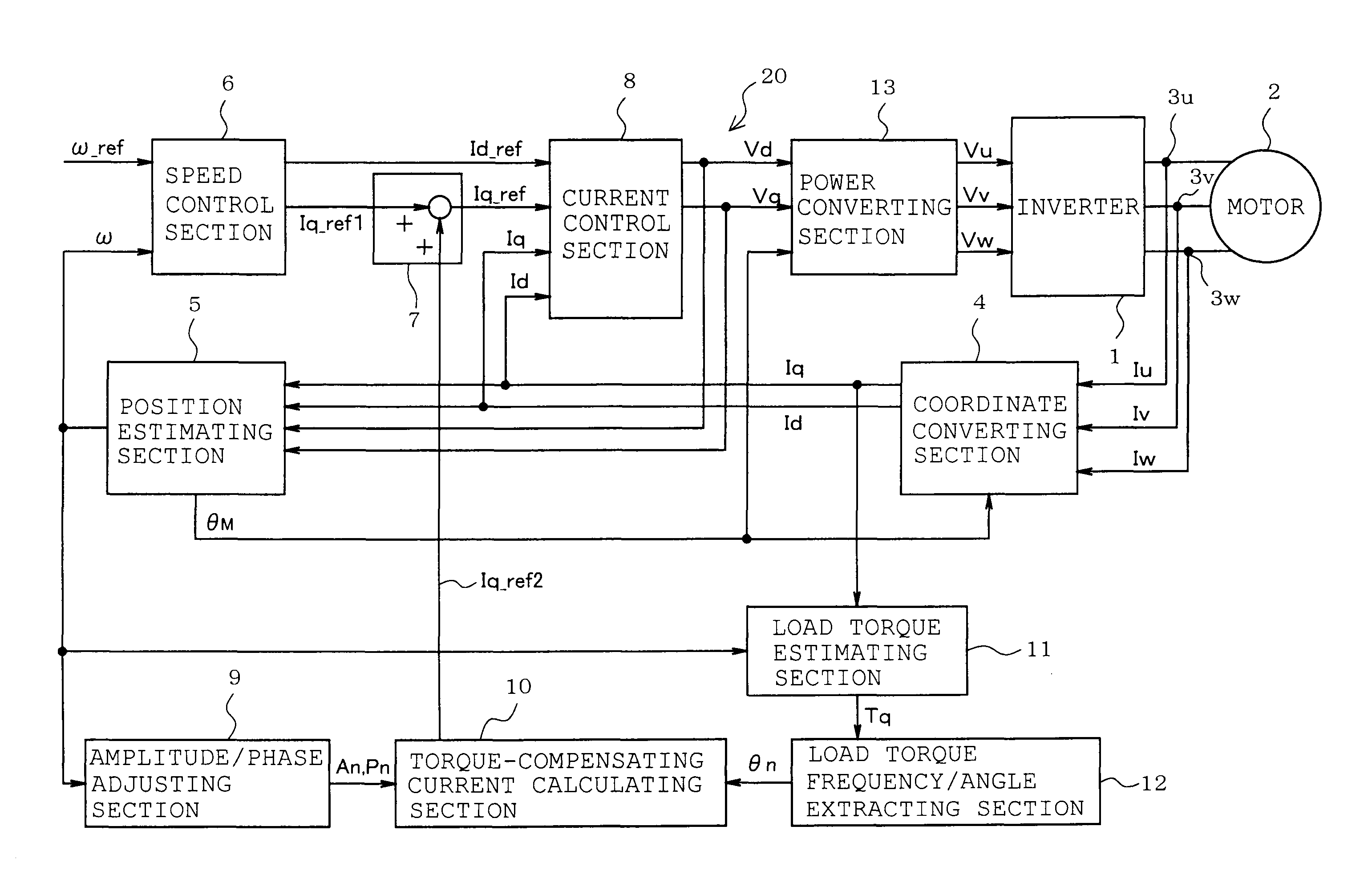
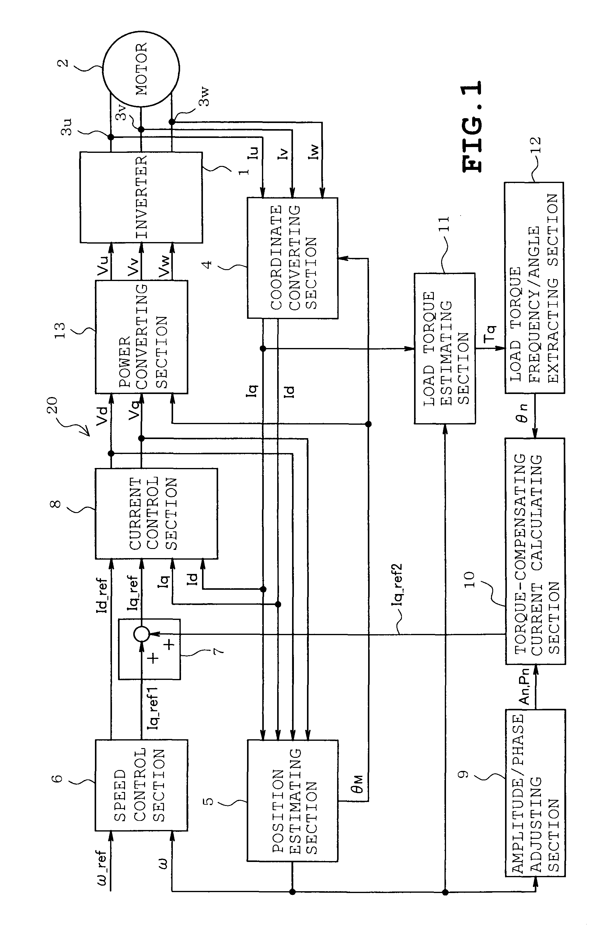
[0019]According to one embodiment, a motor control device comprises an electric power supply unit which supplies AC current to an electric motor driving a load; a current detecting unit which detects current flowing into a winding of the motor; a speed / electrical angle estimating unit which estimates a rotational speed and an electrical angle of the motor, based on the current detected by the current detecting unit; a load torque estimating unit which estimates a load torque to be produced by the load, from a torque current obtained based on the current detected by the current detecting unit and the electrical angle estimated by the speed / electrical angle estimating unit, a motor constant and inertia moment of the motor inclusive of the load; a load torque phase calculating unit which calculates a phase of periodic fluctuation indicated by the load torque; a torque-compensating current determining unit which determines a sinusoidal torque-compensating current, based on the load torq...


PUM


Abstract

A motor control device includes a current detecting unit detecting current flowing into a motor winding, a speed / electrical angle estimating unit estimating a rotational speed and an electrical angle of the motor, based on the current, a load torque estimating unit estimating load torque to be developed by a load, from a torque current obtained based on the current and the electrical angle, a motor constant and inertia moment of the motor inclusive of the load, a load torque phase calculating unit calculating a phase of periodic fluctuation indicated by the load torque, a torque-compensating current determining unit determining a sinusoidal torque-compensating current, based on the load torque phase, and an amplitude / phase adjusting unit detecting speed fluctuation of the motor to adjust amplitude and phase of the torque compensating current by increasing or decreasing the amplitude and the phase so that the speed fluctuation is reduced.

Description

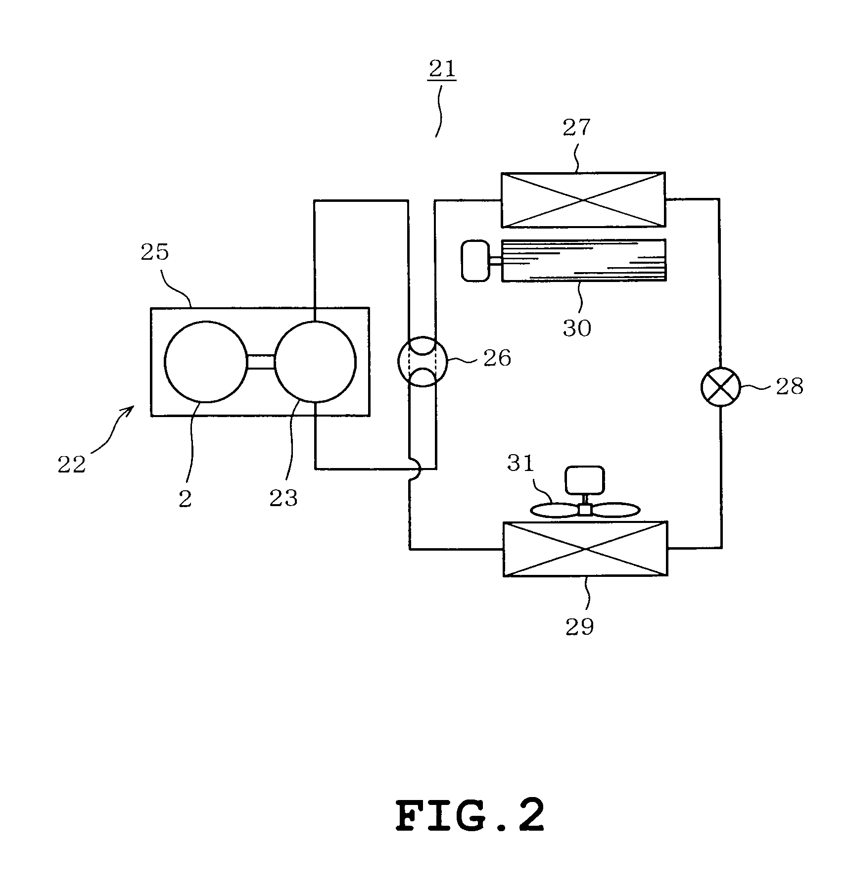
CROSS-REFERENCE TO RELATED APPLICATIONS[0001]This application is based upon and claims the benefit of priority from Japanese Patent Application No. 2010-65997, filed Mar. 23, 2010, the entire contents of which are incorporated herein by reference.FIELD[0002]Embodiments described herein relate to a motor control device which controls an electric motor by a position-sensorless control system and electrical equipment which includes a compressor driven by an electric motor controlled by the motor control device.BACKGROUND ART[0003]For example, when a brushless DC motor is applied to an electric motor driving a compressor or the like, a rotational speed or position of the motor has conventionally been obtained by the use of a position sensor or the like. When the obtained rotational speed differs from a target rotational speed, a current command or a voltage command is changed so that the rotational speed of the motor is adjusted to the target rotational speed. FIG. 11A shows a sectional...

Claims


Application Information

Patent Timeline
Patent Type & Authority Patents(United States)
IPC IPC(8): H02P6/10H02P27/04F04B39/00H02P6/06H02P6/08H02P6/17H02P6/28H02P21/00H02P21/18H02P21/22H02P21/24H02P23/16
CPCH02P23/04F25B49/025
Inventor MAEKAWA, SARI
Owner KK TOSHIBA
Why Eureka
Eureka Blog
Learn More