
Data security in optical communications systems

a technology of optical communication system and data security, applied in the field of optical communication system, can solve the problems of not being widely deployed, sensitive to noise, and difficult for a third party to derive the digital bit sequence encoded by the optical signal

Active Publication Date: 2013-09-17
CIENA
View PDF7 Cites 19 Cited by
  • Summary
  • Abstract
  • Description
  • Claims
  • Application Information

AI Technical Summary

Benefits of technology

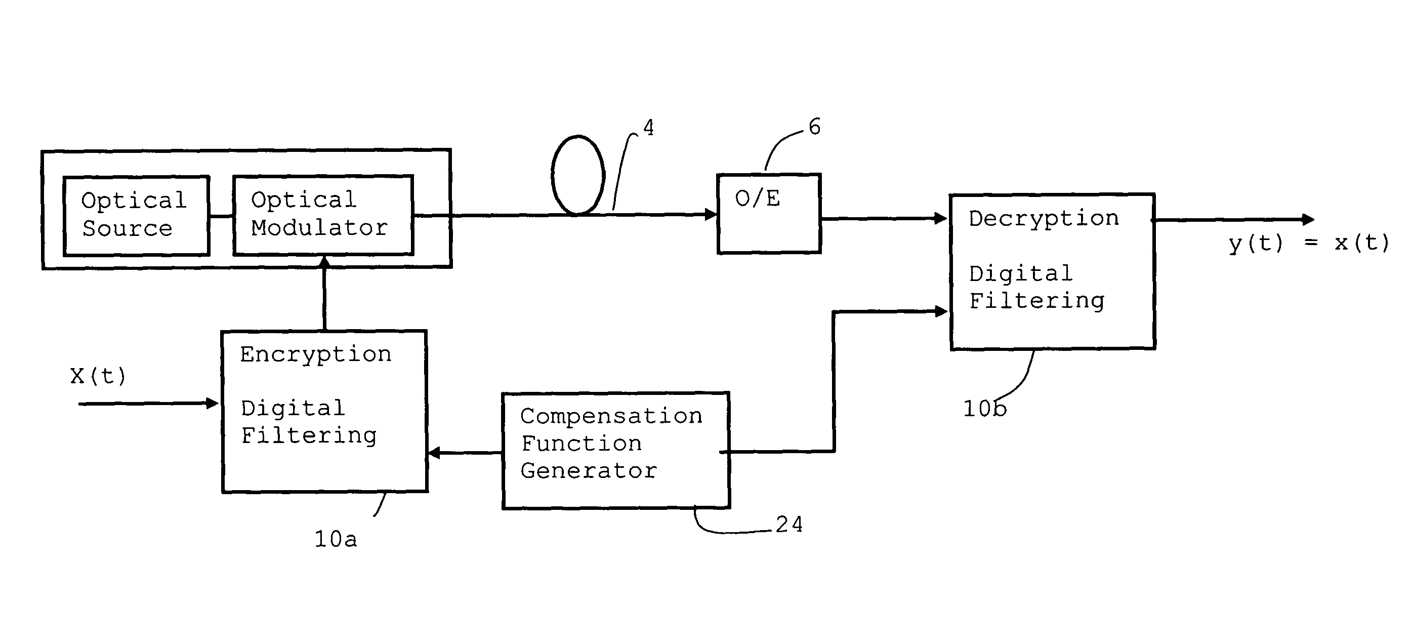
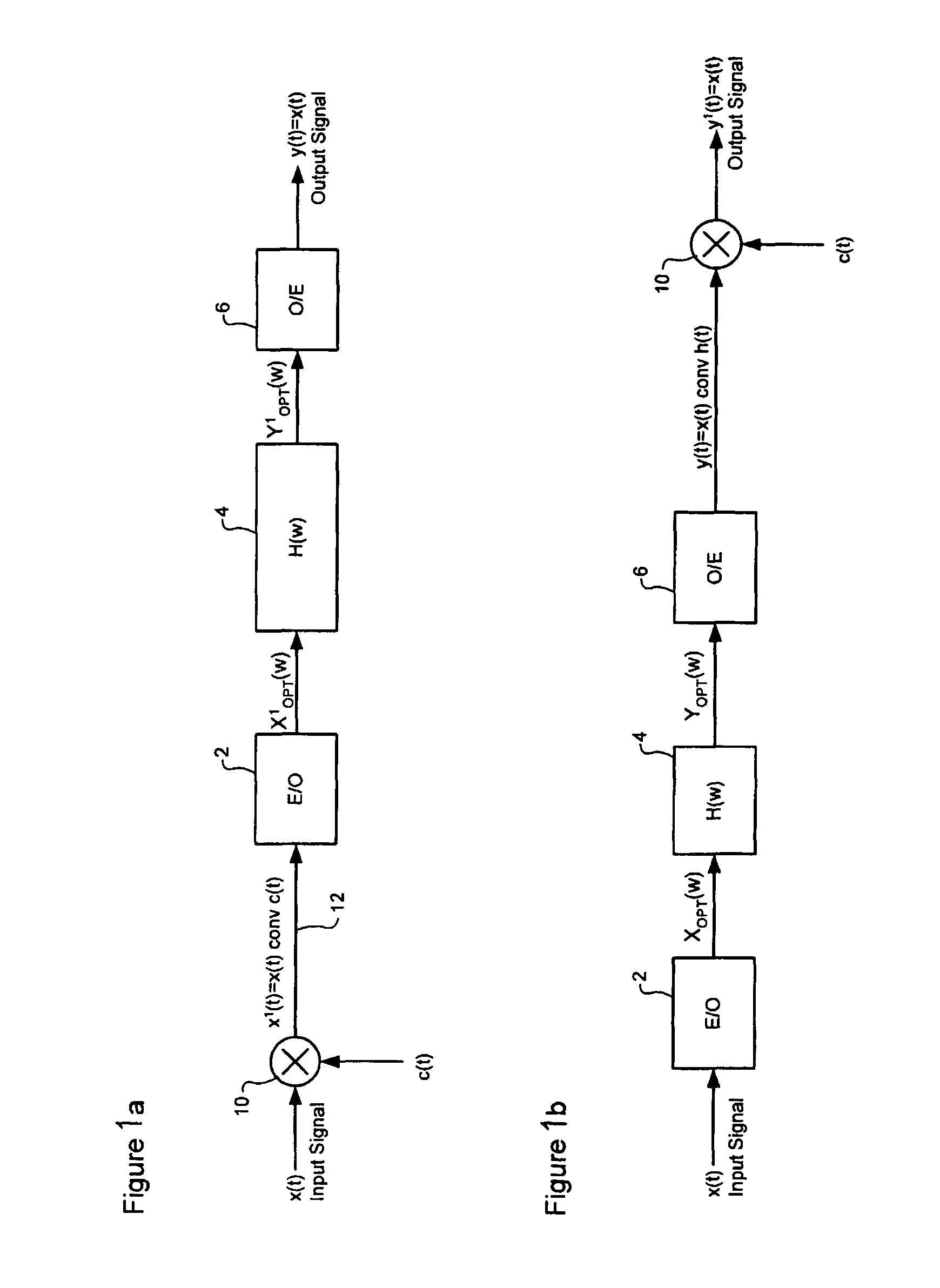
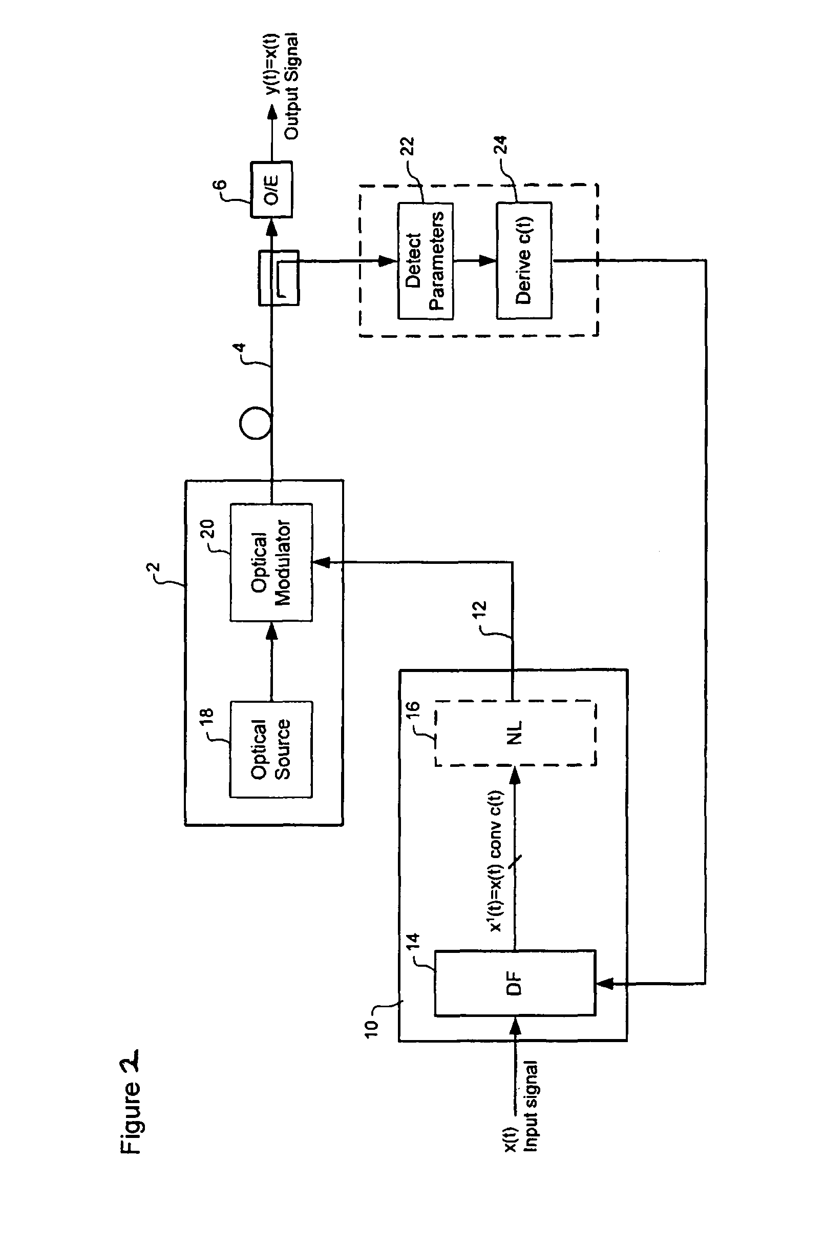
The patent describes a method of processing an electrical signal to create a continuous analog signal for controlling an optical modulator. This makes it difficult for unauthorized individuals to determine the digital bit sequence encoded by the optical signal. The method can also use electrical processing to remove optical transmission impairments, such as dispersion, and provide physical layer security for a small increase in system complexity. Compensation for chromatic dispersion and non-linear effects can be implemented through digital filtering in the transmitter, receiver, or both.

Problems solved by technology

Multi-level coding schemes have been proposed, but are more sensitive to noise than a binary modulation scheme, and are not yet widely deployed.
This makes it difficult for a third party to derive the digital bit sequence encoded by the optical signal.
If it is not possible to quickly convert the intercepted signal into the correct digital bit sequence, cryptanalysis is possible but, at high bit rates, considerably more difficult.
This can result in an order of magnitude or greater increase in the quantity of data to be stored and processed offline to recover the original bit stream.
This is particularly difficult for the case of long haul fiber optic cables where the bit rate is often near the maximum that can be handled by the technology available.
At these rates providing storage of sufficient bit rate, capacity and accuracy can be difficult.

Method used


Image

  • Data security in optical communications systems
  • Data security in optical communications systems
  • Data security in optical communications systems

Examples


Embodiment Construction

[0041]The Assignee has proposed (but not yet published) a system which enables the characteristics of an optical signal to be varied by digital processing of the original electrical signal, in the electrical domain. This ability to pre-process or post-process an optical signal in the electrical domain has been proposed in order to enable compensation of optical distortions, most notably chromatic dispersion.

[0042]Optical communications systems typically include a pair of network nodes connected by an optical waveguide (i.e., fiber) link. Within each network node, communications signals are converted into electrical signals for signal regeneration and / or routing, and converted into optical signals for transmission through an optical link to another node. The optical link between the network nodes is typically made up of multiple concatenated optical components, including one or more (and possibly 20 or more) optical fiber spans (e.g., of 40-150 km in length) interconnected by optical...


PUM


Abstract

A method of encrypting an optical communications signal involves determining an encryption function, filtering an electrical input signal using the encryption function to generate an encrypted electrical signal, and modulating an optical source using the encrypted electrical signal to generate a corresponding encrypted optical signal. This is then transmitted through an optical communications system. The encryption is selected such as to substantially remove symbol definition from the optical signal. This method provides digital signal processing of an electrical input signal in order to derive a signal for controlling an optical modulator in such a way that the optical signal transmitted over the link is a continuous analogue signal rather than a series of discrete symbols which alternate between well-defined signal values. This makes it difficult for a third party to derive the binary bit sequence encoded by the optical signal.

Description

FIELD OF THE INVENTION[0001]The present invention relates to optical communications systems, and in particular to data security within such systems.BACKGROUND OF THE INVENTION[0002]The security afforded to the data being transmitted between the communicating parties is an important consideration when selecting a communications network. Security here refers to the ease with which an unwanted third party can intercept a communication and render it intelligible. In the most security conscious applications a layered approach is taken to security with encryption applied at multiple points within the network, at multiple layers of the OSI stack. Thus all layers of encryption have to be compromised by the eavesdropper before the message can be recovered. For example information may be encrypted at the SONET / SDH (OSI layer 1) in a transmission network and again at higher layers using techniques such as IPSec (OSI layer 3) or TLS (Transport Layer Security, OSI layer 7). In packet based secur...

Claims


Application Information

Patent Timeline
Patent Type & Authority Patents(United States)
IPC IPC(8): H04B10/00
CPCH04B10/2513H04B10/2543H04B2210/252H04B2210/254
Inventor ROBINSON, ALANSPARKS, ADRIANRICKARD, ROBIN
Owner CIENA
Learn More