Plasma confinement structures in plasma processing systems

a plasma processing system and confinement structure technology, applied in the field of plasma confinement structure in plasma processing system, can solve the problems of low energy level of ion bombardment on film removal processes such as sputtering and ion-enhanced etching, and relatively inefficient at the surface of confinement rings, so as to facilitate the processing of substrates

Active Publication Date: 2013-09-24
LAM RES CORP
View PDF114 Cites 162 Cited by
  • Summary
  • Abstract
  • Description
  • Claims
  • Application Information

AI Technical Summary

Problems solved by technology

Since the energy of ions accelerated from the plasma is governed by the sheath potential, a low sheath potential results in a low energy level of ion bombardment on the surfaces of the confinement rings.
Consequently, film removal processes such as sputtering and ion-enhanced etching (such as those occurring during in-situ plasma clean processes) are relatively inefficient at the surface of the confinement rings.
Furthermore, a higher quantity of deposition is left on the surface of the confinement rings after processing due to the low ion bombardment energy.
As a consequence, the substrate throughput rate is disadvantageously reduced, leading to lower productivity and a higher cost of ownership for the plasma processing tool.

Method used


Image

  • Plasma confinement structures in plasma processing systems
  • Plasma confinement structures in plasma processing systems
  • Plasma confinement structures in plasma processing systems

Examples


Embodiment Construction

[0016]The present invention will now be described in detail with reference to a few embodiments thereof as illustrated in the accompanying drawings. In the following description, numerous specific details are set forth in order to provide a thorough understanding of the present invention. It will be apparent, however, to one skilled in the art, that the present invention may be practiced without some or all of these specific details. In other instances, well known process steps and / or structures have not been described in detail in order to not unnecessarily obscure the present invention.

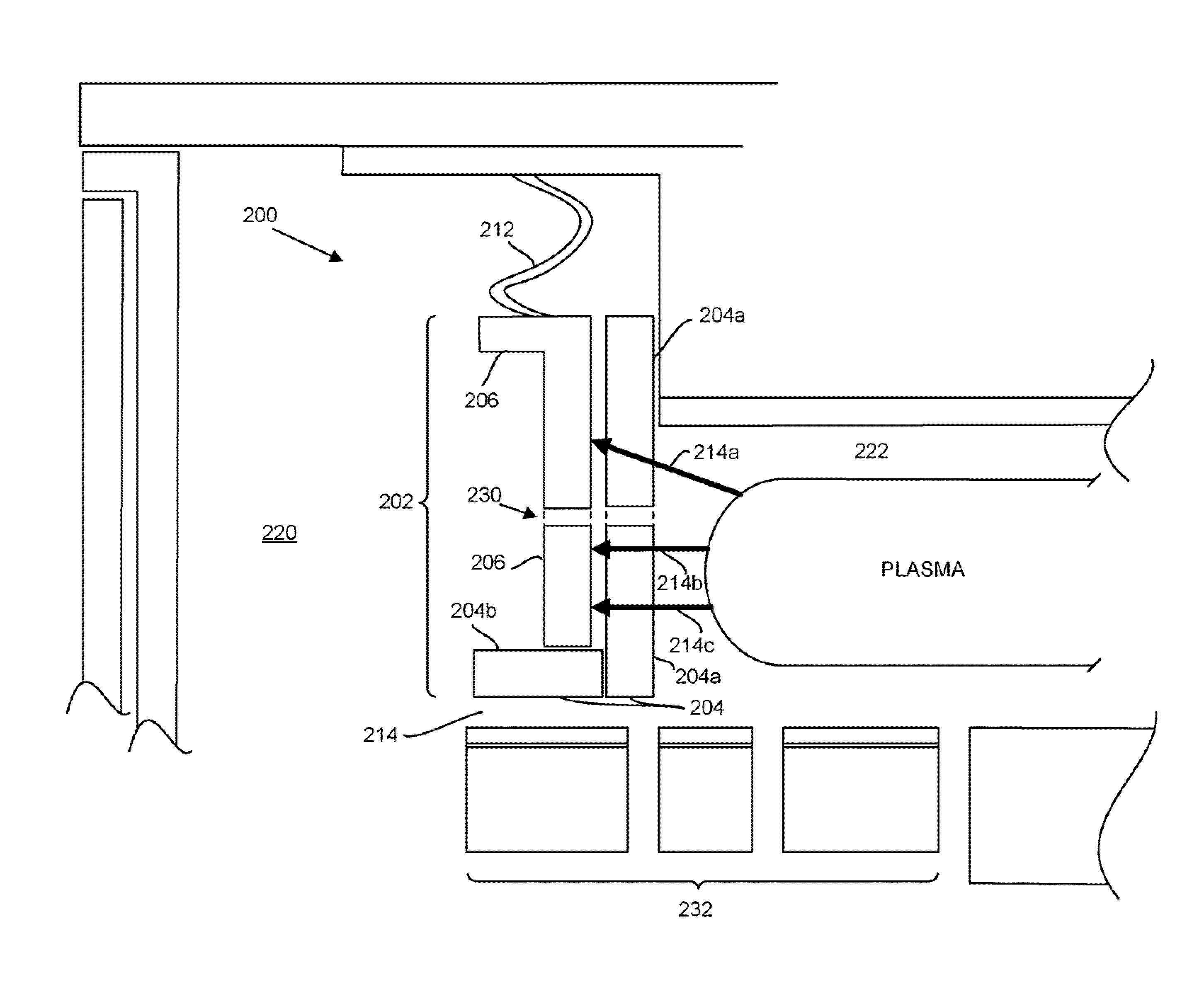
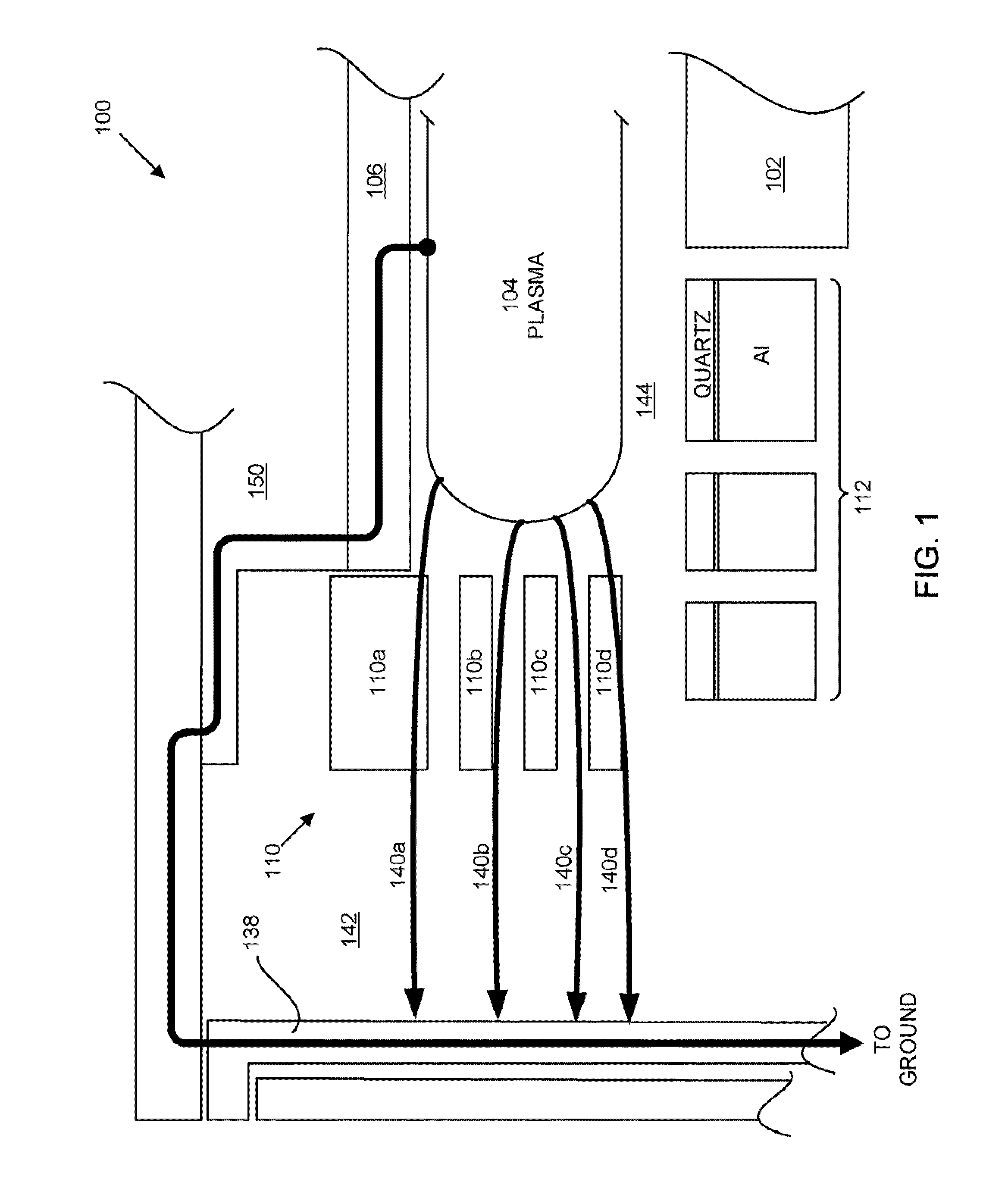
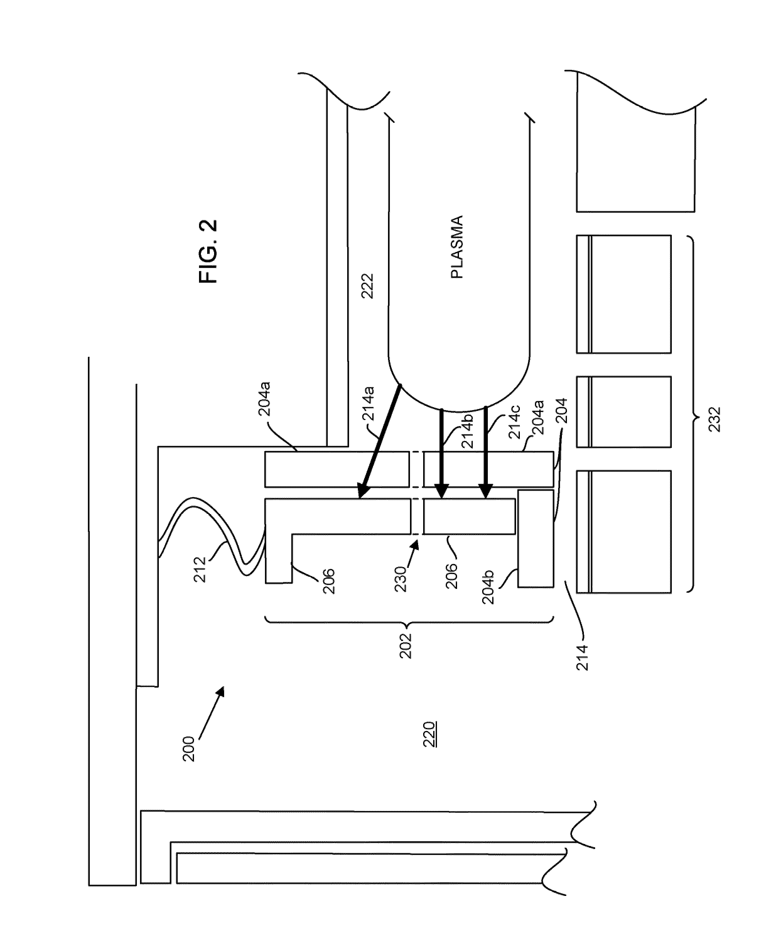
[0017]The inventors herein have noted that when a component is electrically floating, i.e., uncoupled to a DC or an RF ground, the plasma sheath voltage developed at its surface is relatively low in potential. Such is the case with prior art confinement rings, e.g., confinement rings 110 of FIG. 1. In contrast, although there exists a thin layer of quartz on top of annular grounded electrode 112 of ...


PUM

PropertyMeasurementUnit
electrically conductiveaaaaaaaaaa
movable plasma confinementaaaaaaaaaa
flexibleaaaaaaaaaa

Abstract

A movable plasma confinement structure configured for confining plasma in a plasma processing chamber during plasma processing of a substrate is provided. The movable plasma confinement structure includes a movable plasma-facing structure configured to surround the plasma. The movable plasma confinement structure also includes a movable electrically conductive structure disposed outside of the movable plasma-facing structure and configured to be deployed and retracted with the movable plasma-facing structure as a single unit to facilitate handling of the substrate. The movable electrically conductive structure is radio frequency (RF) grounded during the plasma processing. The movable plasma-facing structure is disposed between the plasma and the movable electrically conductive structure during the plasma processing such that RF current from the plasma flows to the movable electrically conductive structure through the movable plasma-facing structure during the plasma processing.

Description

PRIORITY CLAIM[0001]This application is related to and claims priority under 35 U.S.C. §119(e) to a commonly assigned provisional patent application entitled “Plasma Confinement Structures In Plasma Processing Systems,” by Hudson et al., Application Ser. No. 61 / 139,491 filed on Dec. 19, 2008, all of which are incorporated herein by reference.BACKGROUND OF THE INVENTION[0002]Plasma processing systems have long been employed to process substrates (e.g., wafers) in plasma processing systems. In a typical plasma processing chamber, plasma is ignited and confined in a plasma confinement region, which is typically defined by the chamber upper and lower structures, as well as by structures that annularly surround the plasma confinement region.[0003]To facilitate the insertion and removal of substrates, as well as to facilitate the evacuation of exhaust gas from the plasma processing chamber, many chambers employ a set of movable confinement rings to annularly confine the plasma. The movabl...

Claims


Application Information

Patent Timeline
Patent Type & Authority Patents(United States)
IPC IPC(8): C23F1/00H01L21/306C23C16/50C23C16/509C23C16/06C23C16/22
CPCH01J37/32082H01J37/32623C23C16/00C23F1/00Y10T29/49Y10T29/53Y10T29/53961Y10T29/53983Y10T29/49002
Inventor HUDSON, ERICFISCHER
Owner LAM RES CORP
Why Eureka
Try Eureka