Antenna module and antenna unit thereof

a technology of antenna module and antenna unit, which is applied in the direction of resonant antenna, substantially flat resonant element, antenna earthing, etc., can solve the problems of unignored back radiation, unwanted surface wave radiation, and small bandwidth of conventional antenna, and achieve easy mass production and enhance the oblique resonant direction

Active Publication Date: 2013-09-24
MEDIATEK INC +1
View PDF27 Cites 9 Cited by
  • Summary
  • Abstract
  • Description
  • Claims
  • Application Information

AI Technical Summary

Benefits of technology

[0006]Utilizing the antenna unit of the embodiment of the invention, an electric field Ē is formed between the patch, the feed conductor and the opening edge of the second conductive layer to enhance the oblique resonant directions. With the oblique resonant directions, the antenna unit of the embodiment of the invention has broader beamwidth. Additionally, the antenna unit or antenna array module of the embodiments of the invention can be easily mass produced by a standard low-cost PCB process.

Problems solved by technology

Conventional antennas typically have small bandwidths, unignored back radiation and unwanted surface wave radiation issues.

Method used


Image

  • Antenna module and antenna unit thereof
  • Antenna module and antenna unit thereof
  • Antenna module and antenna unit thereof

Examples


Embodiment Construction

[0019]The following description is of the best-contemplated mode of carrying out the invention. This description is made for the purpose of illustrating the general principles of the invention and should not be taken in a limiting sense. The scope of the invention is best determined by reference to the appended claims.

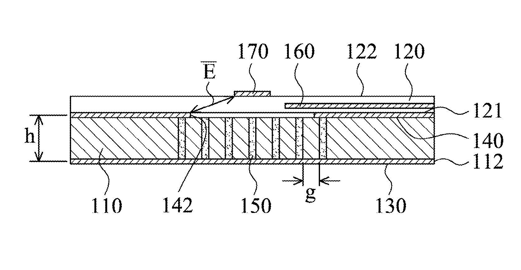
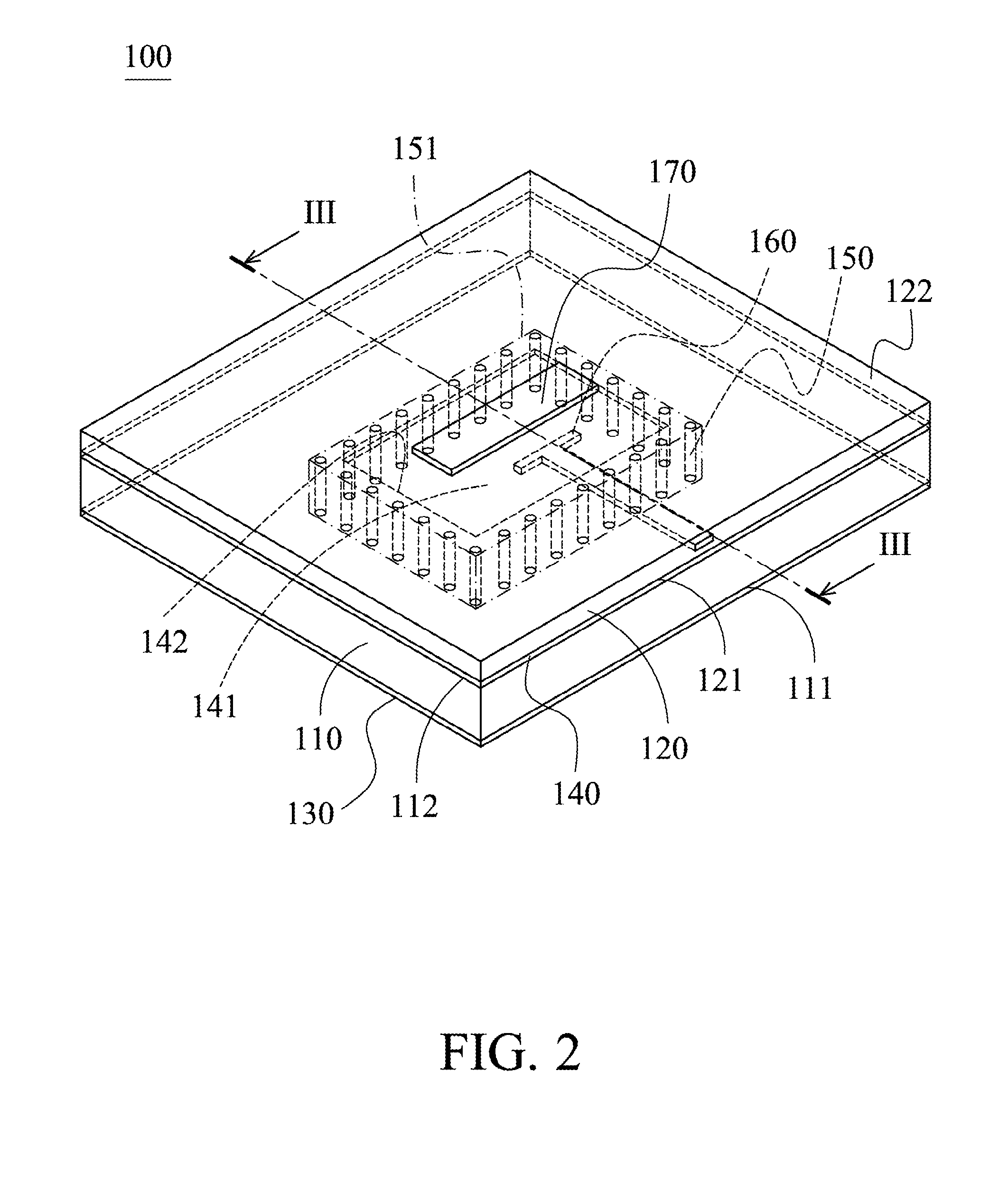
[0020]FIG. 2 shows an antenna unit 100 of an embodiment of the invention. The antenna unit 100 includes a first substrate 110, a second substrate 120, a first conductive layer 130, a second conductive layer 140, a plurality of conductive vias 150, a feed conductor 160 and a patch 170. The first substrate 110 includes a first surface 111 and a second surface 112, wherein the first surface 111 is opposite to the second surface 112. The second substrate 120 includes a third surface 121 and a fourth surface 122, the third surface 121 is opposite to the fourth surface 122. The first conductive layer 130 is disposed on the first surface 111. The second conductive layer 140 i...


PUM


Abstract

An antenna unit is provided. The antenna unit includes a first substrate, a first conductive layer, a second conductive layer, a plurality of conductive vias, a feed conductor and a patch. The first substrate includes a first surface and a second surface, wherein the first surface is opposite to the second surface. The first conductive layer is disposed on the first surface. The second conductive layer is disposed on the second surface, wherein an opening is formed on the second conductive layer, and the opening has an opening edge. The conductive vias are formed in the first substrate and connect the first conductive layer to the second conductive layer, wherein the conductive vias surround the opening to define a cavity. The feed conductor extends above the opening to feed a wireless signal to the antenna unit. The patch is disposed above the opening and is separated from the feed conductor.

Description

BACKGROUND OF THE INVENTION[0001]1. Field of the Invention[0002]The present invention relates to an antenna module, and in particular relates to an antenna module and cavity-backed stacked planar antenna unit thereof.[0003]2. Description of the Related Art[0004]FIG. 1 shows a conventional antenna 1, including an antenna substrate 10, a feed substrate 20, a microstrip patch 30, a ground plane 40 and a microstrip feed line 50. The antenna substrate 10 includes a first surface 11 and a second surface 12. The feed substrate 20 includes a third surface 21 and a fourth surface 22. The microstrip patch 30 is disposed on the first surface 11. The ground plane 40 is disposed on the third surface 21. The second surface 12 is connected to the ground plane 40. A coupling aperture 41 is formed on the ground plane 40. The microstrip feed line 50 is disposed on the fourth surface 22. The microstrip feed line 50 feeds wireless signals via the coupling aperture 41 to the microstrip patch 30. Convent...

Claims


Application Information

Patent Timeline
Patent Type & Authority Patents(United States)
IPC IPC(8): H01Q1/38
CPCH01Q21/065H01Q9/045
Inventor LIN, YI-CHENGCHEN, HO-CHUNGHUNG, KUO-FONG
Owner MEDIATEK INC
Why Eureka
Try Eureka