
Exhaust purification device for internal combustion engine

a purification device and internal combustion engine technology, applied in machines/engines, metal/metal-oxide/metal-hydroxide catalysts, metal/metal-oxide/metal-hydroxide catalysts, etc., can solve the problems of inability to promote nox reduction, limited operating conditions, and increased combustion noise, so as to increase the amount of exhaust-gas recirculation, increase the amount of fuel injection, increase the effect of exhaust-gas recirculation

Inactive Publication Date: 2013-10-08
HONDA MOTOR CO LTD
View PDF36 Cites 2 Cited by
  • Summary
  • Abstract
  • Description
  • Claims
  • Application Information

AI Technical Summary

Benefits of technology

The patent describes a method to reduce and purify nitrogen oxides (NOx) from the exhaust of an internal combustion engine. By using a fuel reformer to produce a reducing gas, even at low temperatures, the exhaust can be made into a reducing atmosphere, allowing for efficient purification of NOx using a NOx purification catalyst. The reducing gas can also help to quickly heat up the engine and improve NOx purification efficiency. This technology can be used in a variety of vehicles and engines.

Problems solved by technology

In addition, in a case of, immediately after startup of the engine, there being a state in which the lean NOx catalyst has not achieved the activation temperature, reduction of NOx cannot be promoted, even if the exhaust air-fuel ratio is made low by supplying such a reducing agent.
Moreover, when enriching the exhaust air-fuel ratio by a method of rich combustion as described above, the operating conditions are limited.
For example, during high-load operation in which combustion is sharp, the combustion noise grows worse.
In addition, during low-load operation such as immediately after startup of the engine or while idling, the charge efficiency into the cylinders decreases and combustion may become unstable.

Method used


Image

  • Exhaust purification device for internal combustion engine
  • Exhaust purification device for internal combustion engine
  • Exhaust purification device for internal combustion engine

Examples


Embodiment Construction

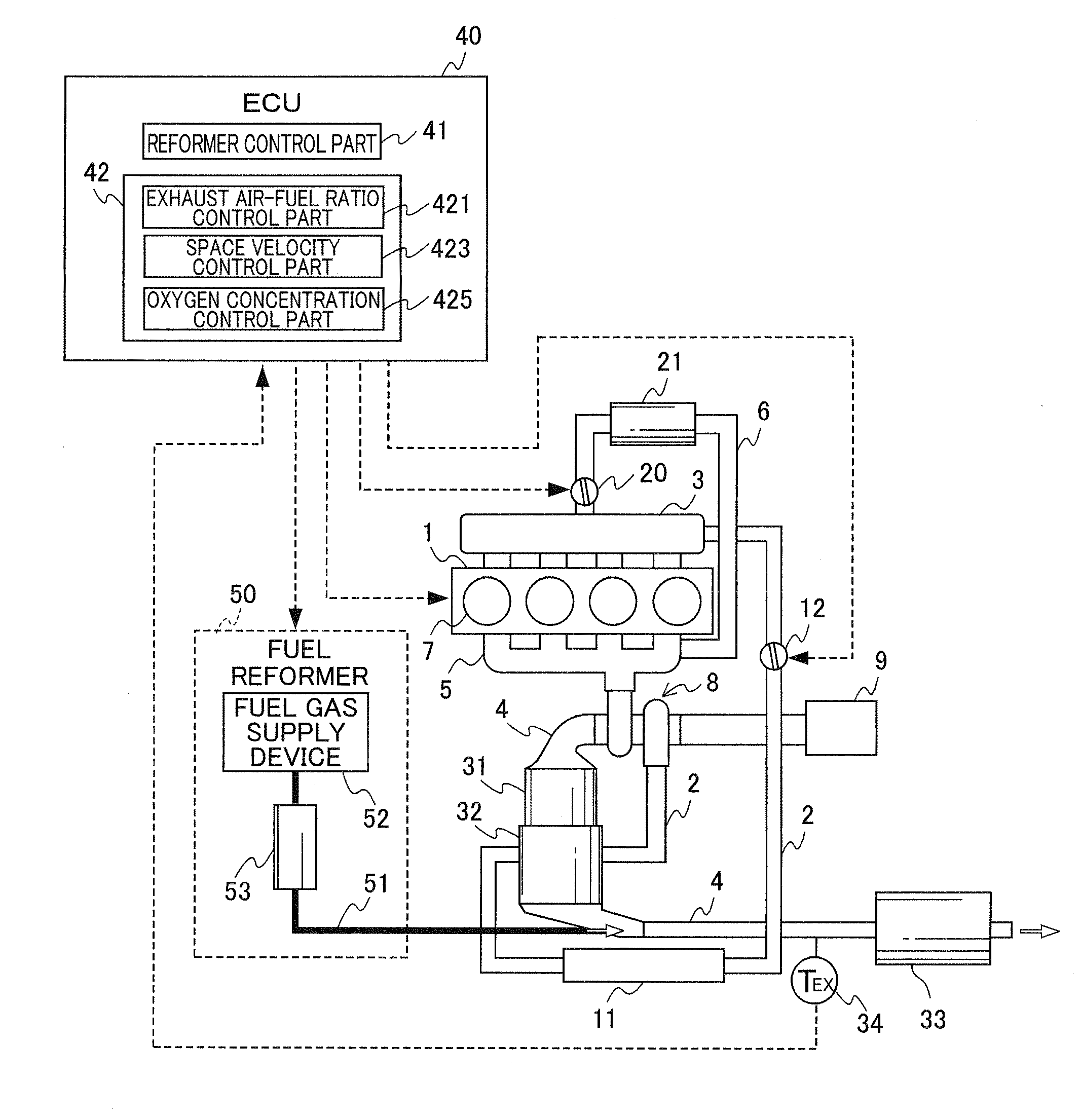
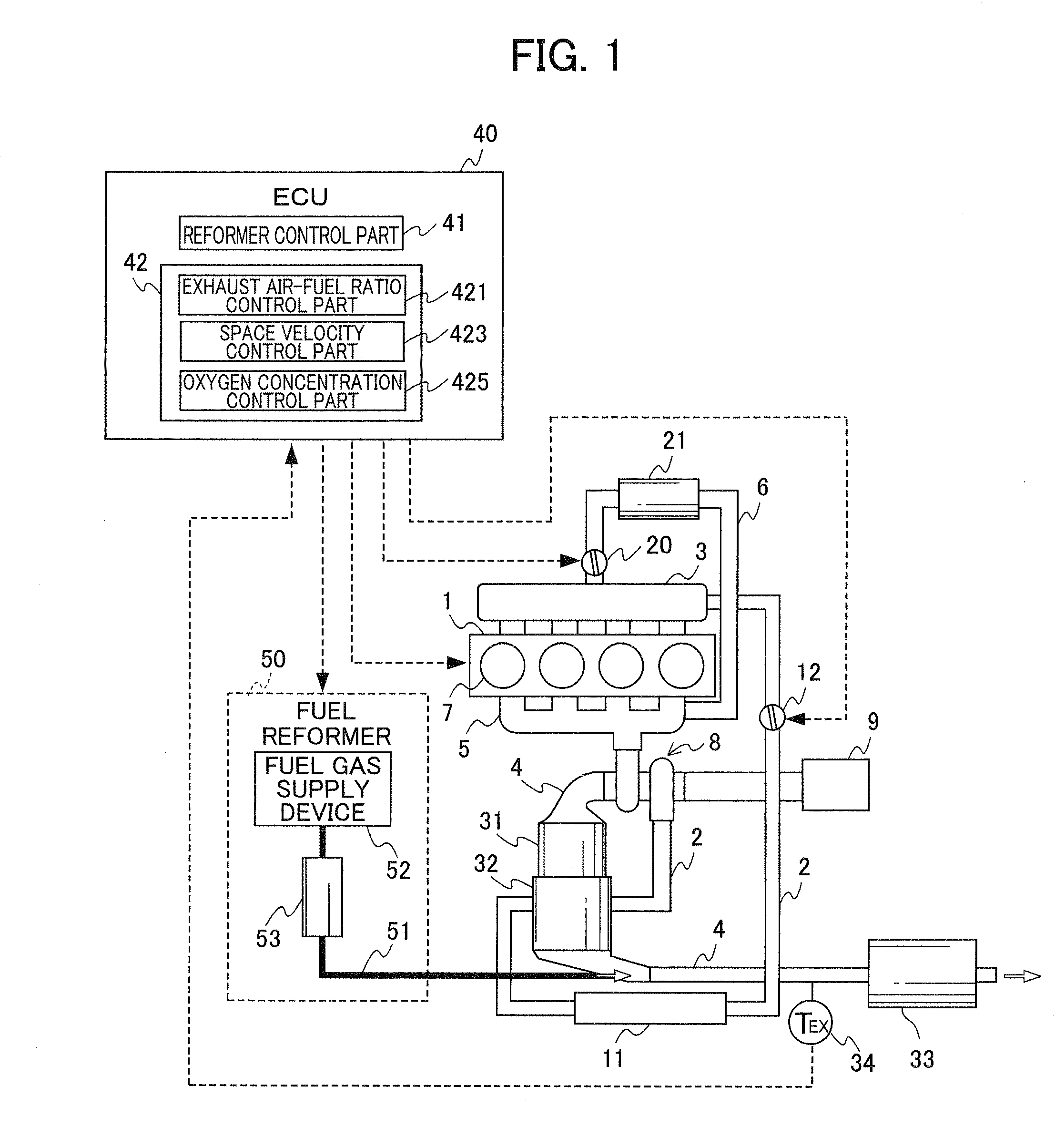
[0069]FIG. 1 is a view showing a configuration of an internal combustion engine and the exhaust purification device thereof according to an embodiment of the present invention. An internal combustion engine (hereinafter referred to as “engine”) 1 is a diesel engine that directly injects fuel into combustion chambers and combusts the fuel by way of compression ignition, and uses diesel oil as the fuel. In addition, a fuel injector, which is not illustrated, is provided to the combustion chamber of each cylinder 7. These fuel injectors are electrically connected to an electronic control unit (hereinafter referred to as “ECU”) 40, and the valve-open duration and the valve-close duration of the fuel injectors, i.e. the fuel injection amount and fuel injection timing, are controlled by the ECU 40.

[0070]The engine 1 is provided with intake plumbing 2 as an intake path in which intake air flows, exhaust plumbing 4 as an exhaust path in which exhaust gas flows, an exhaust-gas recirculation ...


PUM

PropertyMeasurementUnit
temperatureaaaaaaaaaa
NOx adsorption capacityaaaaaaaaaa

Abstract

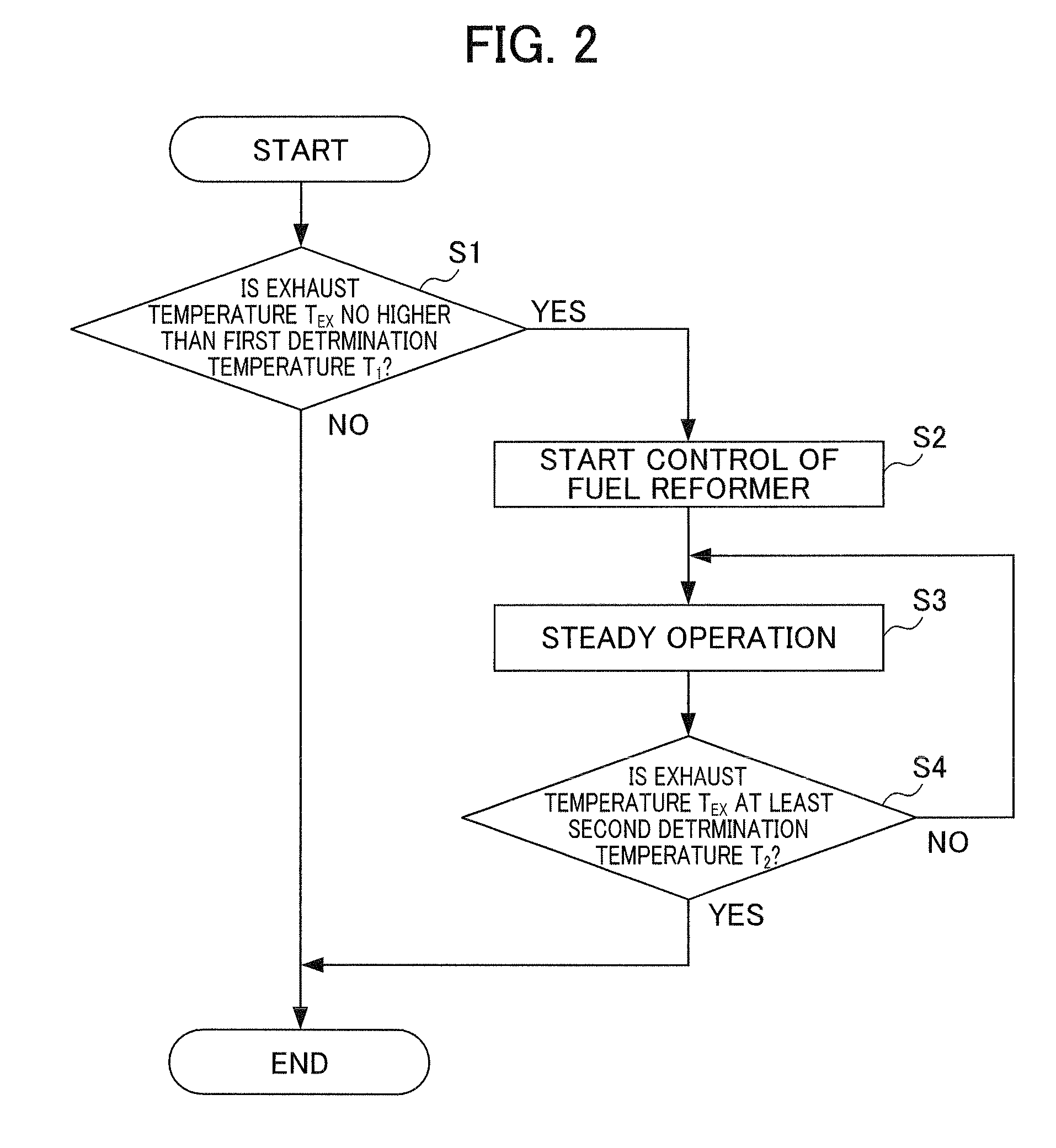
An exhaust purification device for an internal combustion engine is provided that can promote the reduction of NOx in a NOx purification catalyst from immediately after startup of the internal combustion engine. The exhaust purification device includes: a fuel reformer that is provided separately from exhaust plumbing 4, reforms fuel and produces a reducing gas that contains carbon monoxide, hydrogen and hydrocarbons, and supplies the reducing gas upstream of the NOx purification catalyst into the exhaust path; an exhaust gas temperature sensor 34 that detects a temperature TEX of the exhaust flowing in the exhaust plumbing 4; and a reformer control part 41 that starts supply of the reducing gas to the exhaust plumbing 4 by starting control of the fuel reformer 50 in a case where the temperature TEX thus detected by this exhaust gas temperature sensor 34 is no higher than a predetermined first determination temperature T1, and stops the supply of reducing gas to the exhaust plumbing 4 by stopping control of the fuel reformer 50 in a case where the temperature detected by the exhaust gas temperature sensor 34 is at least a second determination temperature T2, which is higher than the first determination temperature.

Description

CROSS-REFERENCED TO RELATED APPLICATION[0001]This application is a National Stage entry of International Application No. PCT / JP2008 / 070072, filed Nov. 5, 2008, which claims priority of JP 2007-322568, filed Dec. 13, 2007. The disclosure of the prior application is hereby incorporated in its entirety by reference.TECHNICAL FIELD[0002]The present invention relates to an exhaust purification device for an internal combustion engine. More specifically, it relates to an exhaust purification device for an internal combustion engine provided with a NOx purification catalyst that purifies NOx in exhaust gas.BACKGROUND ART[0003]Conventionally, a lean NOx catalyst has been known in which, when the exhaust is an oxidizing atmosphere, (when the concentration of oxygen in the exhaust is high relative to the concentration of reducing components (HC, CO)), nitrogen oxides (NOx) in the exhaust is absorbed, and when the exhaust is a reducing atmosphere (when the concentration of reducing components ...

Claims


Application Information

Patent Timeline
Patent Type & Authority Patents(United States)
IPC IPC(8): F01N3/00
CPCB01D53/9495B01J23/002B01J23/63B01J29/7615B01J37/0244B01J37/0246C01B3/38C01B3/386F01N3/206F01N3/2066F01N9/00B01D2251/202B01D2251/204B01D2251/208B01D2255/1021B01D2255/1025B01D2255/2065B01D2255/2092B01D2255/50B01D2258/012B01J2523/00C01B2203/0233C01B2203/0244C01B2203/0261C01B2203/06C01B2203/107C01B2203/1082C01B2203/1604F01N2240/30F01N2610/04B01J2523/3706B01J2523/3712B01J2523/3718B01J2523/48B01J2523/828Y02T10/47Y02T10/24Y02P20/52Y02T10/12Y02T10/40
Inventor IWAMOTO, JUNMOTOHASHI, GOMIKAMI, HITOSHIISHIMARU, SHINYAWADA, KATSUJI
Owner HONDA MOTOR CO LTD
Learn More