Mercury recovery apparatus

Inactive Publication Date: 2005-03-15
PANASONIC CORP
View PDF17 Cites 1 Cited by
  • Summary
  • Abstract
  • Description
  • Claims
  • Application Information

AI Technical Summary

Benefits of technology

According to this construction, the entire portions of phosphor powder placed in the distillation vessel can be heated uniformly. This can facilitate vaporization and separation of mercury from the phosphor powder. Therefore, the temperature of middle portions of the phosphor powder in the distillation vessel can be increased to a temperature necessary for thermal decomposition of mercury compounds, without excessively increasing a heating temperature by the heating unit. Also, be

Problems solved by technology

Here, rare-earth phosphors, which are expensive, are often used in fluorescent lamps for general lighting.
However, with the above-described conventional wet-method, a portion of the phosphor powder is dissolved into the aqueous solution containing active sulfur, with the crystal structure of phosphors being destroyed or changed.
This causes characteristics of the phosphor powder including luminance to deteriorate, making recycling of the treated phosphor powder impossible.
Further, unlike the dry-method mercury recovery, the wet-method mercury recovery generally requires special equipment for liquid-waste treatment, including treatment of used aqueous solutions etc.
Therefore, the wet-method mercury recovery t

Method used


Image

  • Mercury recovery apparatus
  • Mercury recovery apparatus
  • Mercury recovery apparatus

Examples


first embodiment

(First Embodiment)

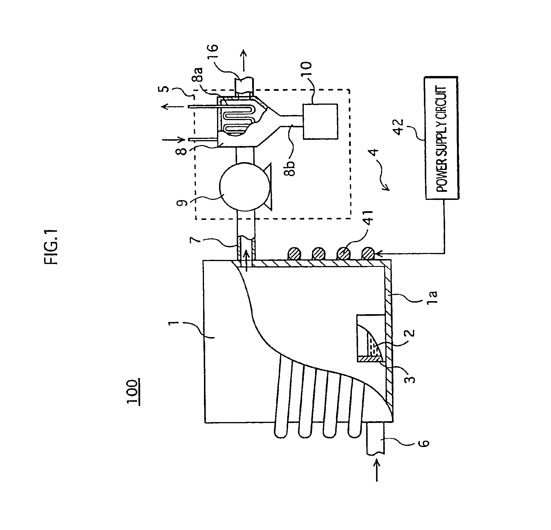
FIG. 1 shows the construction of a mercury recovery apparatus 100 that is used to realize a mercury recovery method according to the first embodiment of the present invention.

As shown in the figure, the mercury recovery apparatus 100 includes a cylindrical reaction vessel 1 that is made of metal and can be hermetically sealed, a cylindrical distillation vessel 3 that is set on the bottom of the reaction vessel 1 and into which a mixture 2 of mercury-containing phosphor powder and an organic reducing agent is to be placed, a heating apparatus 4 that heats the mixture 2 placed in the distillation vessel 3 to vaporize and separate mercury from the phosphor powder, and a mercury collection unit 5 that pumps in the mercury vapor from the reaction vessel 1, and cools and condenses the mercury vapor to collect the mercury.

The distillation vessel 3 is made of a stainless steel and is detachable from a bottom la of the reaction vessel 1. Also, a pipe 6 for supplying gases, ...

experimental examples

The following describes experimental examples that can verify the effect of the mercury recovery method relating to the first embodiment.

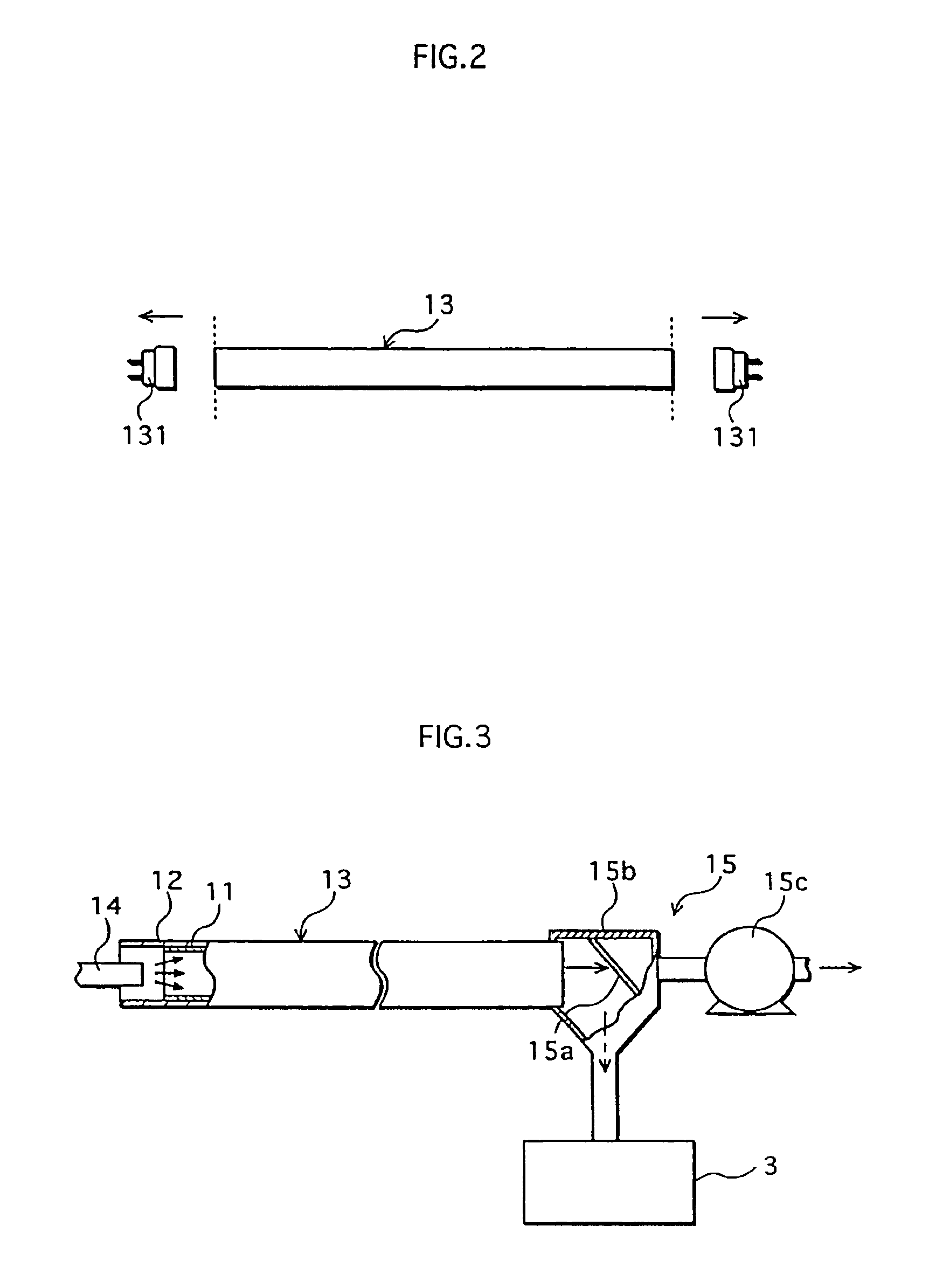
First, phosphor powder was detached from a waste straight-tube fluorescent lamp 13 with rated power of 40 W whose life has been expired. Phosphors used in this waste fluorescent lamp 13 are rare-earth phosphors with the following compositions:

Red phosphorY2O3:EuBlue phosphor(SrCaBa)5(PO4)3Cl:EuGreen phosphorLaPO4:Tb, Ce

An amount of mercury contained in the detached phosphor powder, that is, phosphor powder from which mercury was yet to be separated (hereafter simply referred to as “untreated phosphor powder”) was 2800 μg per phosphor powder 2 g.

To prepare a mixture A (practical example 1), the untreated phosphor powder was mixed with an aqueous solution in which oxalic acid was being dissolved, at a rate of oxalic acid 0.4 g (20 wt %) to phosphor powder 2 g.

To prepare a mixture B (practical example 2), the untreated phosphor powder was mixed with a...

second embodiment

(Second Embodiment)

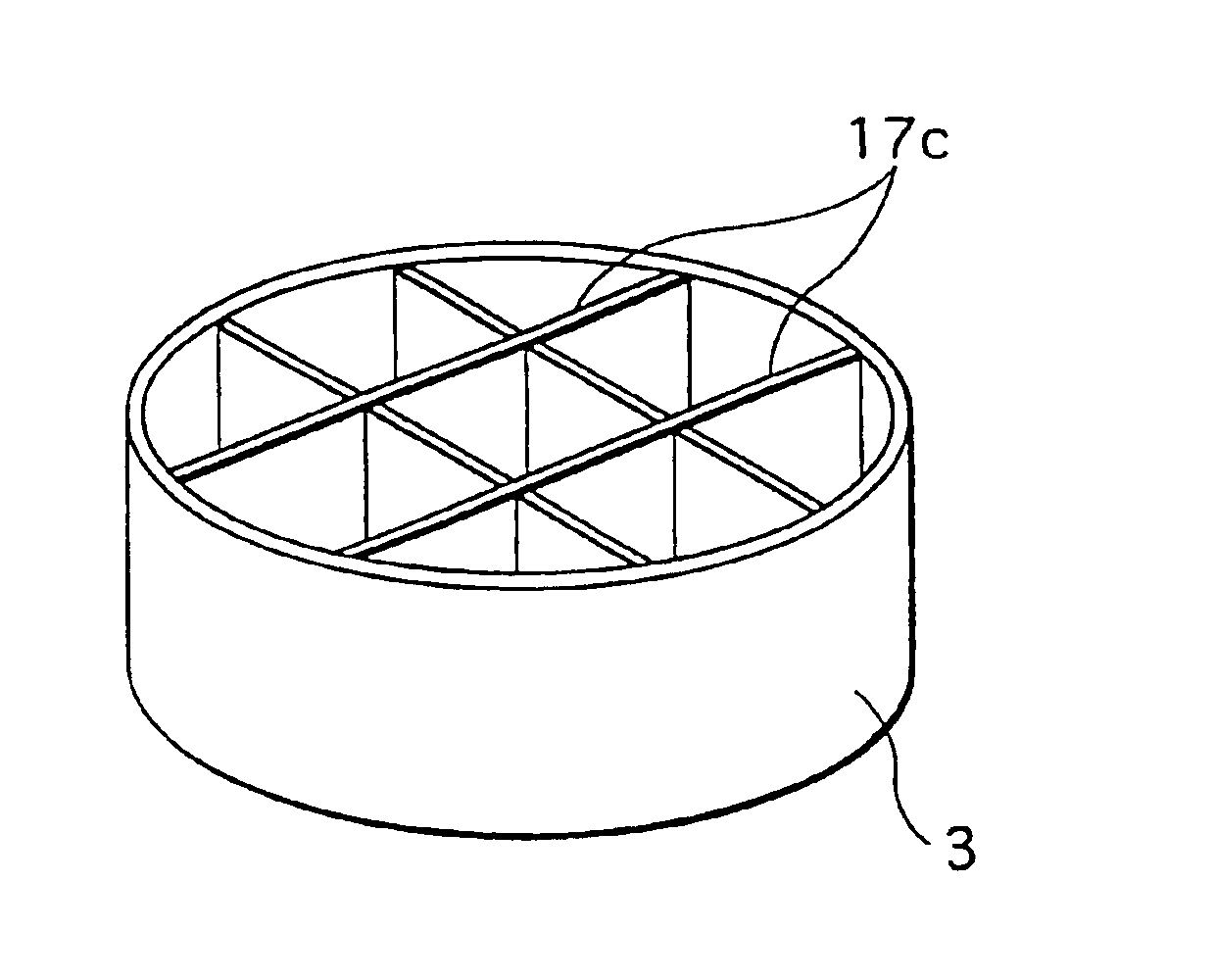
The following descries a mercury recovery apparatus according to a second embodiment of the present invention. This mercury recovery apparatus has the same construction as the mercury recovery apparatus 100 (FIG. 1) used to realize the mercury recovery method in the first embodiment, except that a dividing member 17 made of a heat conductive material is provided in the distillation vessel 3. Accordingly, the present embodiment is described focusing only on the distillation vessel 3.

FIG. 7A is a perspective view showing one example of the distillation vessel 3 in the second embodiment. As shown in the figure, three stainless cylindrical members each having a different diameter that form the dividing member 17 are placed substantially concentrically within the distillation vessel 3. FIG. 7B schematically shows the state where heat is transmitted to phosphor powder 20 within the distillation vessel 3 in the reaction vessel 1. For ease of explanation, the figure shows...


PUM

PropertyMeasurementUnit
Electrical conductivityaaaaaaaaaa
Diameteraaaaaaaaaa
Electrical conductoraaaaaaaaaa

Abstract

Both ends of a bulb of a waste fluorescent lamp are cut off, a phosphor layer formed on an interior surface of the bulb is detached, so that mercury-containing phosphor powder can be obtained. The mercury-containing phosphor powder is subjected to a heating and reducing process with the dry-method, by mixing an organic reducing agent with the phosphor powder and heating the mixture, to vaporize and separate mercury from the phosphor powder. The vaporized mercury is then cooled and condensed, to collect mercury.

Description

BACKGROUND OF THE INVENTION(1) Field of the InventionThe present invention relates to a mercury recovery method and a mercury recovery apparatus, and particularly to a technique for separating and collecting mercury contained in phosphors used in fluorescent lamps.(2) Related ArtMercury, which is a toxic material, is used in lighting devices such as fluorescent lamps. When fluorescent lamps whose life is expired or fluorescent lamps that are found defective during manufacturing processes (hereafter simply referred to as “waste fluorescent lamps”) are disposed, mercury is usually to be recovered from the waste fluorescent lamps. The recovered mercury is processed to remove impurities etc., and then is recycled.As a method for recovering mercury from phosphor powder used in waste fluorescent lamps, the wet-method is conventionally known, one example of which is disclosed in Japanese laid-open patent application No. H10-12149. According to the disclosed method, mercury-containing phosp...

Claims


Application Information

Patent Timeline
IPC IPC(8): C22B43/00C22B7/00C22B5/00B09B3/00B01D3/00B01D3/34B09B5/00C22B5/02C22B9/02
CPCC22B5/00C22B43/00C22B7/001Y02P10/20
Inventor FUJIWARA, KENJIFUJINAMI, KIYOKATSU
Owner PANASONIC CORP
Why Eureka
Try Eureka