Fuel cell, fuel cell system, and electronic device

a fuel cell and fuel cell technology, applied in the direction of fuel cells, fuel cell details, electrical devices, etc., can solve the problems of deterioration of anode electrodes, low power generation efficiency, and exhausted unreacted fuel, and achieve the effect of inhibiting

Inactive Publication Date: 2010-09-30
SONY CORP
View PDF10 Cites 1 Cited by
  • Summary
  • Abstract
  • Description
  • Claims
  • Application Information

AI Technical Summary

Benefits of technology

[0015]In particular, according to the fuel cell system of the embodiment of the invention, in a state of stopping power generation, in the case where a voltage generated in the power generation section becomes a certain voltage value or less, the fuel is supplied to the fuel electrode. Thus, without separately providing a new mechanism for injecting inactive gas or water, oxygen pooled on the fuel electrode side is able to be removed, and increase of oxygen partial pressure is able to be inhibited. Therefore, deterioration of the anode electrode at the time of stopping power generation is able to be effectively inhibited.

Problems solved by technology

However, in Japanese Unexamined Patent Application Publication No. 2007-80658 in which the exhaust hole is provided in the vaporized fuel container, there has been a possibility that unreacted fuel is exhausted to lower power generation efficiency.
Further, since the exhaust hole provided in the side wall of the vaporized fuel container is directly open outward, there has been a possibility that external air intrudes into the vaporized fuel container through the exhaust hole while the fuel cell stops power generation, and the anode electrode is deteriorated by oxygen contained in the external air when the fuel cell is restarted.
However, in the method of Japanese Unexamined Patent Application Publication No. 2006-85931, since the fuel cell body is contained into the airtight container, the number of parts is increased and the device size is jumboized, leading to increased cost.

Method used


Image

  • Fuel cell, fuel cell system, and electronic device
  • Fuel cell, fuel cell system, and electronic device
  • Fuel cell, fuel cell system, and electronic device

Examples


first embodiment

[0035]1. Whole structure of a fuel cell

2. Method of manufacturing the fuel cell

second embodiment (

example of a fuel cell system including the fuel cell of the invention)

1. Structure of the fuel cell system

2. Operation of the fuel cell system

Example

[0036]Modified examples (modified examples of a through hole and a groove)

Application example

First Embodiment

Whole Structure of a Fuel Cell

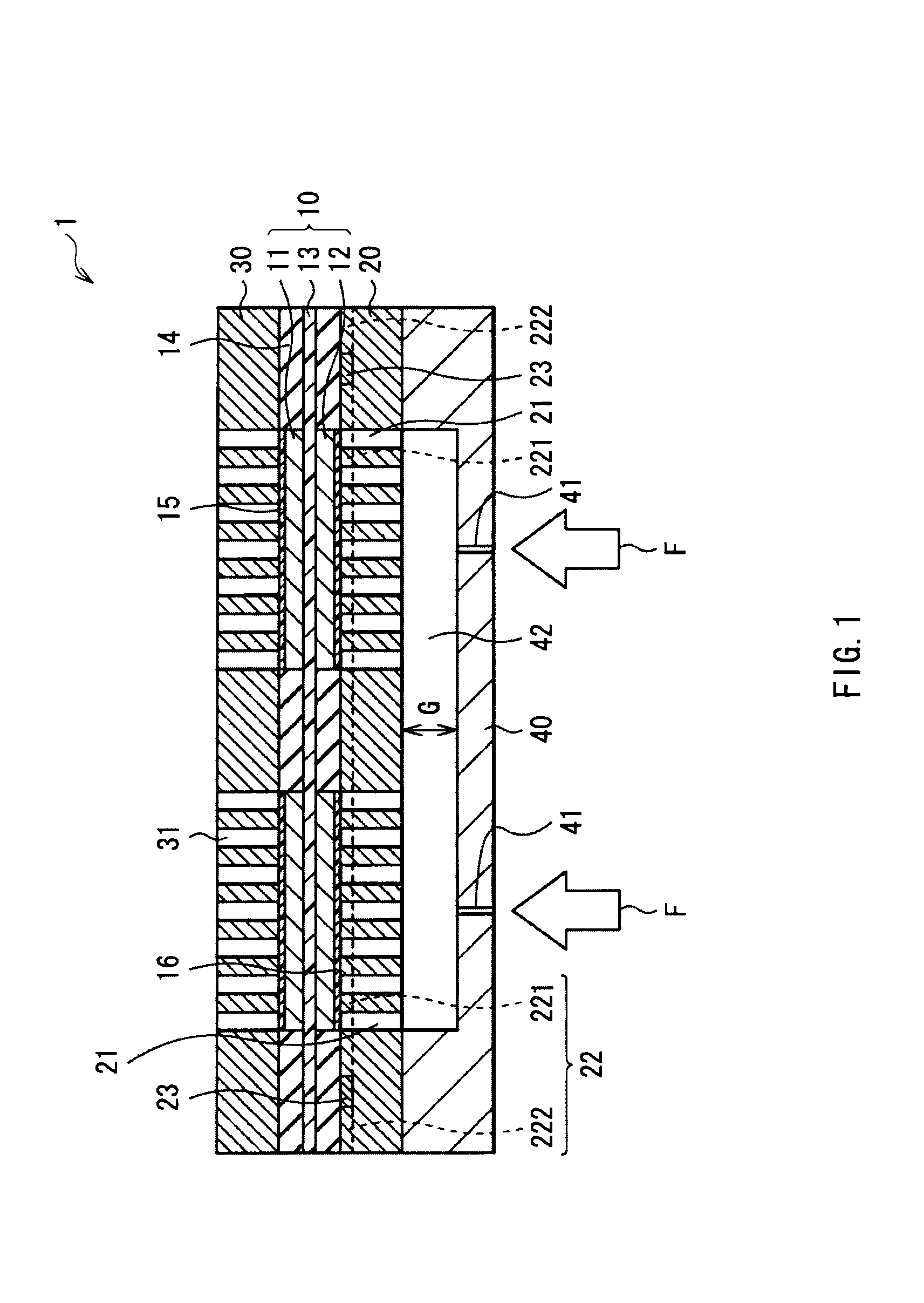
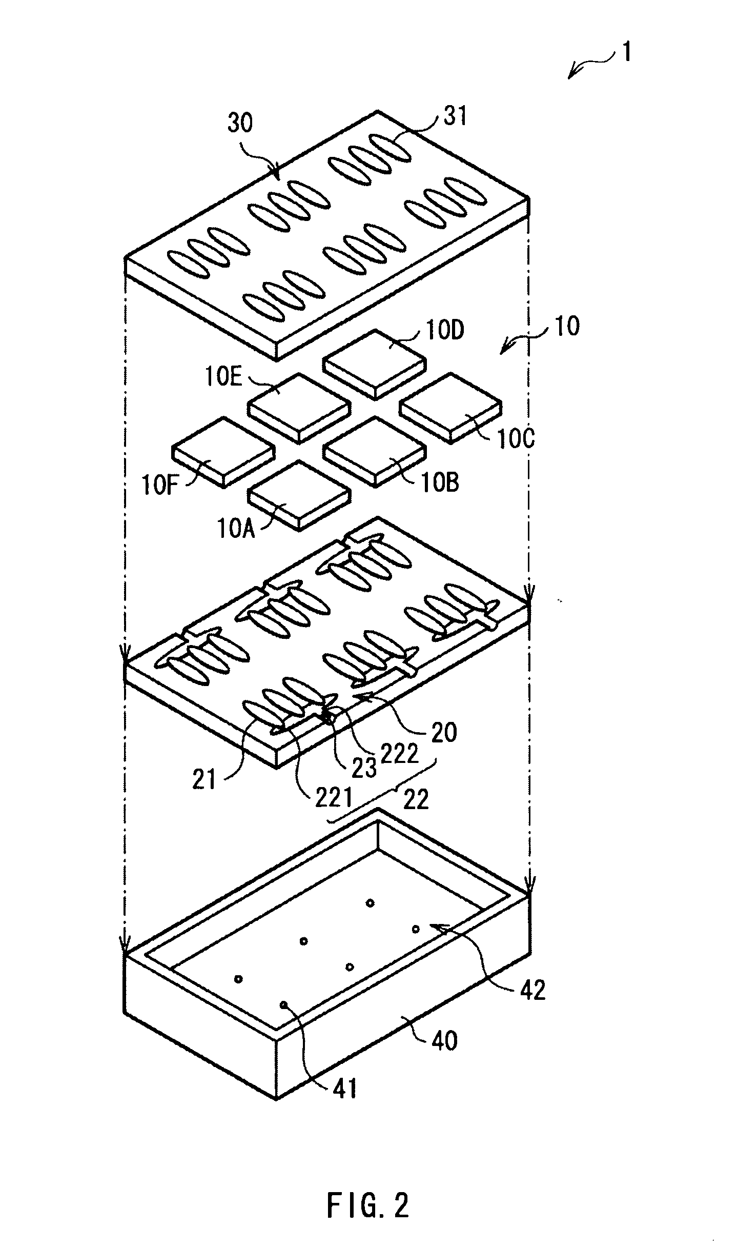
[0037]FIG. 1 illustrates a cross sectional structure of a fuel cell according to a first embodiment of the invention. FIG. 2 illustrates an exploded view of the fuel cell illustrated in FIG. 1. The fuel cell 1 is used, for example, as a power source of a mobile electronic device such as a mobile phone and a notebook PC (Personal Computer). The fuel cell 1 includes an anode side platy member 20 and a cathode side platy member 30 on both sides of a power generation section 10.

[0038]The power generation section 10 is a Direct Methanol Fuel Cell for performing power generation by reaction between methanol and oxygen. The power generation section 10 includes one or a plurality of unit cells 10A to 10F (f...

second embodiment

Whole Structure of a Fuel Cell System

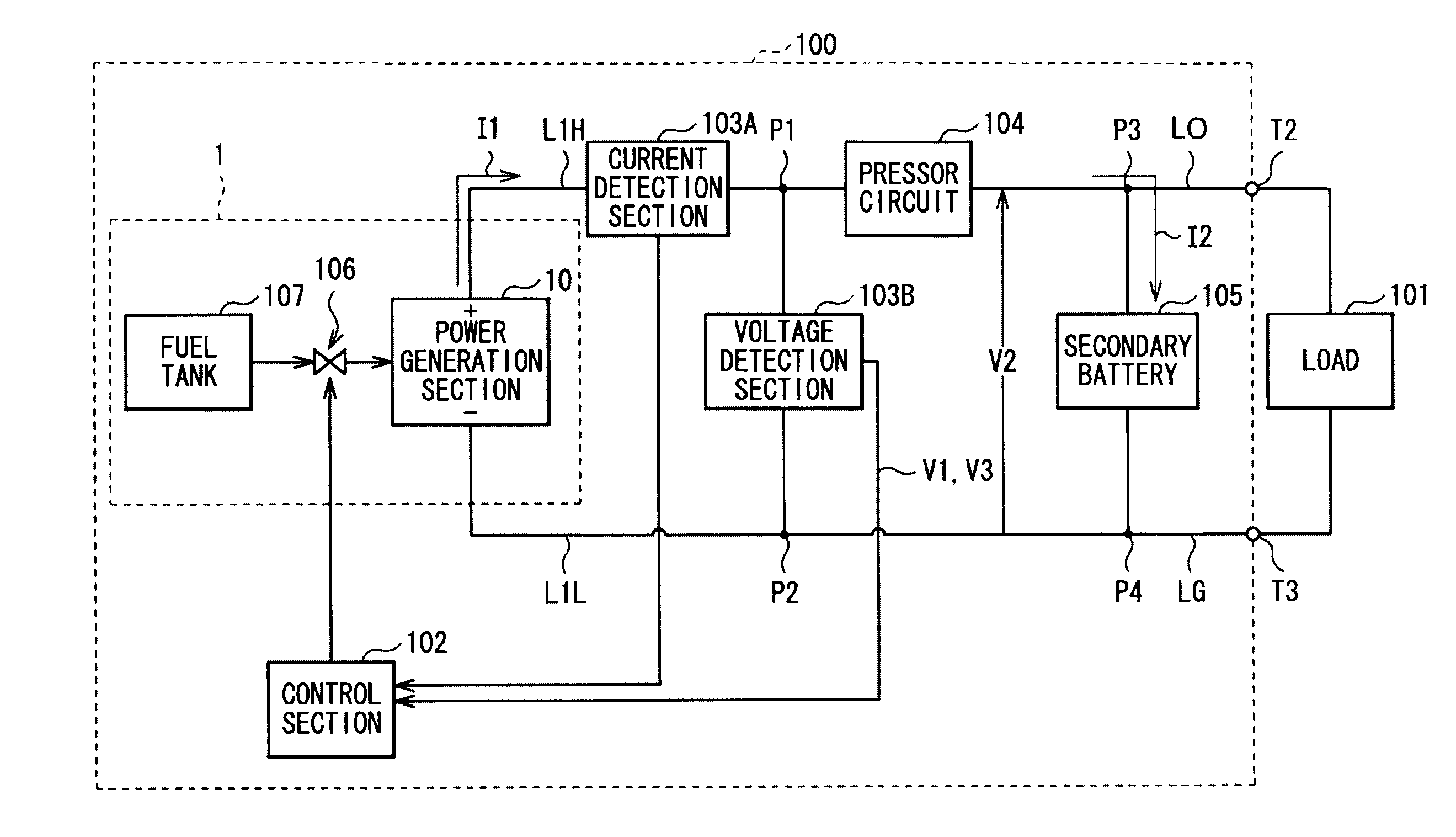
[0068]FIG. 8 illustrates a whole structure of a fuel cell system (fuel cell system 100) according to a second embodiment of the invention. The fuel cell system 100 drives a load 101 by power generation of the fuel cell 1 described in the foregoing first embodiment, or charges a secondary battery 105. The fuel cell system 100 is composed of, for example, the fuel cell 1, a current detection section 103A, a voltage detection section 103B, a pressor circuit 104, the secondary battery 105, and a control section 102. For the sections overlapped with the sections in the first embodiment, the description thereof will be omitted.

[0069]The fuel cell 1 includes the power generation section 10, a fuel pump 106, and a fuel tank 107. The fuel tank 107 stores a liquid fuel necessary for power generation (for example, methanol or methanol water solution). The fuel pump 106 pumps up the liquid fuel stored in the fuel tank 107, supplies (transports) the liquid fu...


PUM

PropertyMeasurementUnit
thickaaaaaaaaaa
voltageaaaaaaaaaa
voltageaaaaaaaaaa

Abstract

A fuel cell with which deterioration of an anode electrode is able to be inhibited by an inexpensive means while generated carbon dioxide is removed, a fuel cell system including the same, and an electronic device including the same are provided. The fuel cell includes: a power generation section having an electrolyte between a cathode electrode and an anode electrode; an anode side platy member provided on the anode electrode side of the power generation section; a fuel vaporization chamber; a through hole that is formed in the anode platy member and gives passage between the anode electrode and the fuel vaporization chamber; a carbon dioxide exhaust section that guides carbon dioxide generated in the power generation section to each side face of the anode platy member or the fuel vaporization chamber; and a valve provided in the carbon dioxide exhaust section.

Description

BACKGROUND OF THE INVENTION[0001]1. Field of the Invention[0002]The present invention relates to a fuel cell performing power generation by reaction between methanol or the like and oxygen, a fuel cell system including the same, and an electronic device including the same.[0003]2. Description of the Related Art[0004]As a power source of a small electronic device such as a mobile personal computer, applying a fuel cell has been considered. As a fuel for the fuel cell, a liquid fuel with a high energy density (for example, methanol) is desirably used.[0005]In some case, the fuel is supplied as a dilute liquid fuel to an anode electrode. In addition, a vaporization type fuel cell in which a fuel not diluted but vaporized is supplied to an anode electrode has been considered (for example, see Japanese Unexamined Patent Application Publication Nos. 2007-80658 and 2006-85931). In Japanese Unexamined Patent Application Publication No. 2007-80658, after the vaporized fuel is once contained ...

Claims


Application Information

Patent Timeline
Patent Type & Authority Applications(United States)
IPC IPC(8): H01M8/04H01M8/02
CPCH01M8/0258H01M8/04089H01M8/04201Y02E60/523H01M8/0668H01M8/1011H01M16/006H01M8/04559H01M8/2457Y02E60/10Y02E60/50H01M8/2459H01M8/2483
Inventor KUMAGAE, KIYOSHI
Owner SONY CORP
Why Eureka
Try Eureka