Method and apparatus for delivering a cased glass stream

a glass stream and stream technology, applied in vacuum blowing machines, blowing machines, manufacturing tools, etc., can solve the problems of air bubbles, sometimes termed “blisters,” in the casing glass stream, and is difficult to fill the cracks and passages of the casing glass spout, so as to prevent air from permeating the stream

Inactive Publication Date: 2005-02-01
OWENS-BROCKWAY GLASS CONTAINER INC
View PDF14 Cites 1 Cited by
  • Summary
  • Abstract
  • Description
  • Claims
  • Application Information

AI Technical Summary

Benefits of technology

Apparatus for forming a cased glass stream having an inner core glass surrounded by an outer casing glass in accordance with a presently preferred embodiment of the invention includes a spout for delivering core glass from a first source through a first orifice. A second orifice is vertically spaced beneath and aligned with the first orifice, and is surrounded by an annular chamber that communicates with the second orifice through a gap between the first and second orifices. A tube delivers casing glass to the annular chamber from the outlet opening of a casing glass spout in such a way that glass continuously flows by gravity through the orifices from the first and second sources to form the cased glass stream. A hollow spout tube within the casing glass spout is positioned with respect to the spout outlet opening for metering flow of casing glass through the outlet opening and delivery tube to the annular chamber surrounding the orifices. The interior of this spout tube is coupled to a source of gas under pressure so as to maintain the tube interior and the interior of the thin fall of casing glass through the spout outlet opening at a pressure above ambient pressure surrounding the casing glass spout. This elevated gas pressure within the casing glass fall reverses the pressure differential between the interior and exterior of the spout outlet opening, so that any tendency for air to migrate through the refractory material surrounding the outlet opening and into the casing glass fall is eliminated.
In accordance with another aspect of the present invention, there is provided an apparatus for delivering a glass stream that includes a glass spout having a lower outlet opening and a flow control spout tube disclosed within the spout. The spout tube has a closed upper end, a hollow interior and an open lower end adjacent to the spout outlet opening, and position of the tube within the spout is controlled so as to control flow of glass through the outlet opening. The hollow interior of the flow control tube is coupled to a source of gas under pressure so as to maintain the tube interior at a pressure above that of ambient air surrounding the spout. Thus, a third aspect of the invention contemplates a method of preventing permeation of air through the refractory material around the spout outlet opening into the glass flowing through the outlet opening by delivering gas under pressure to the flow control tube so as to maintain gas pressure within the tube and within the spout outlet opening above ambient air pressure around the spout. By way of example, gas pressure within the flow control tube and the spout outlet opening may be maintained at a pressure of about two inches of water column above ambient. The gas maintained under pressure within the spout tube may comprise air, nitrogen or argon. In some applications, such as manufacture of amber glass, it may be desirable to provide a reducing gas within the spout tube and in contact with the glass flow, which would thus advantageously change the nature of the atmosphere in contact with the glass flow. For example, methane or another combustible gas may be injected into the spout tube to bum and maintain a reducing atmosphere at elevated pressure in contact with the glass flow.

Problems solved by technology

For example, the presence of air bubbles, sometimes termed “blisters,” in the casing glass stream has been a problem.
However, continued use of the ceramic spout requires that the described “flooding” operation be undertaken with increasing frequency, apparently due to increasing erosion and wear of the spout material.
It is believed that, as the refractory spout material ages, it becomes more difficult to fill the air migration cracks and passages within casing glass spout.
In any event, the described “flooding” operation detracts from glass production, and therefore undesirably increases production costs.
Furthermore, production of cased glass having air bubbles or blisters in the casing layer results in undesirably increased scrap rates, further increasing production costs.

Method used


Image

  • Method and apparatus for delivering a cased glass stream
  • Method and apparatus for delivering a cased glass stream
  • Method and apparatus for delivering a cased glass stream

Examples


Embodiment Construction

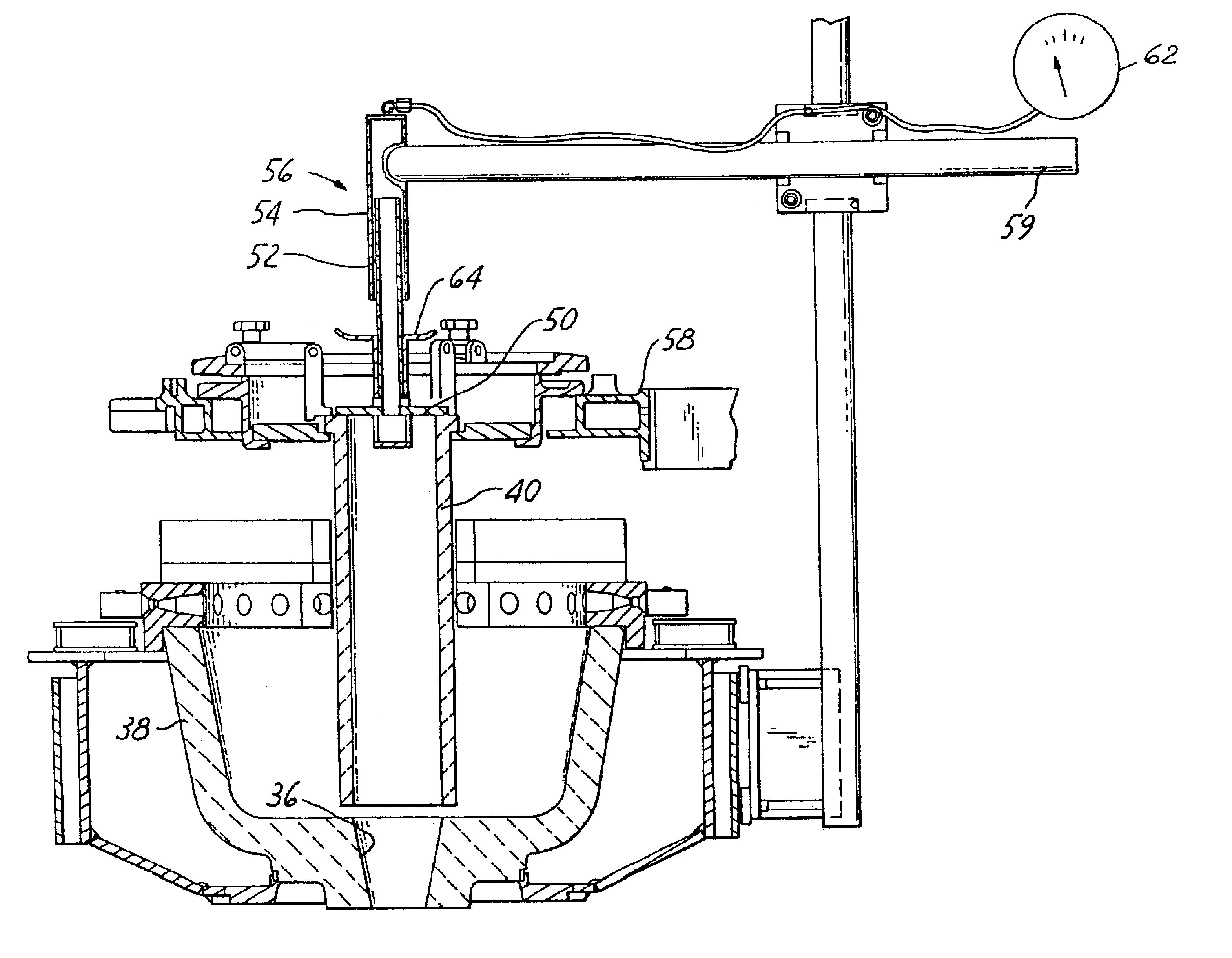
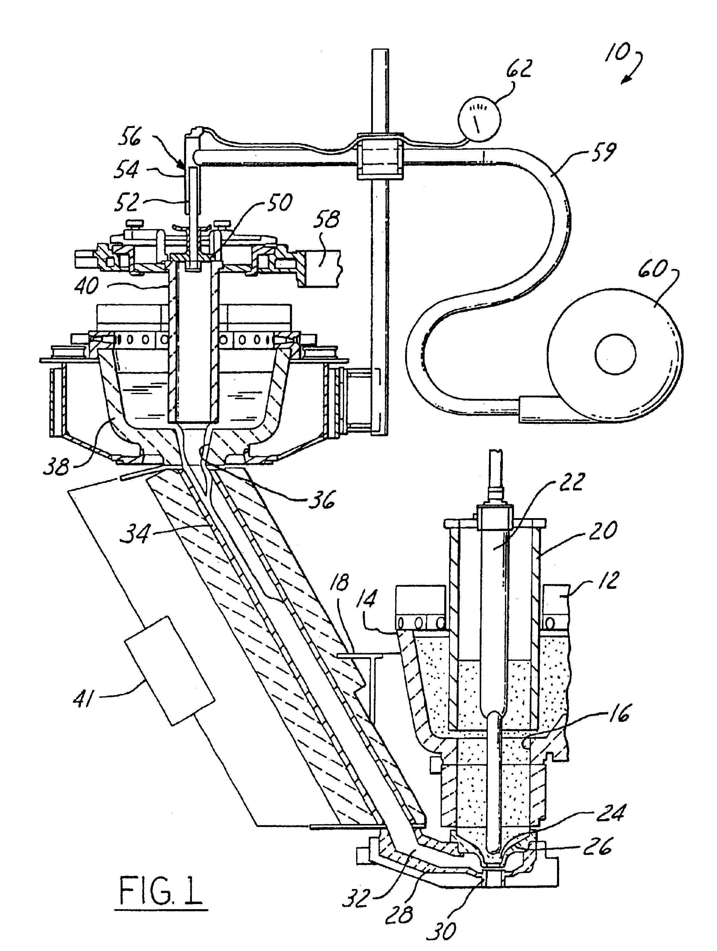
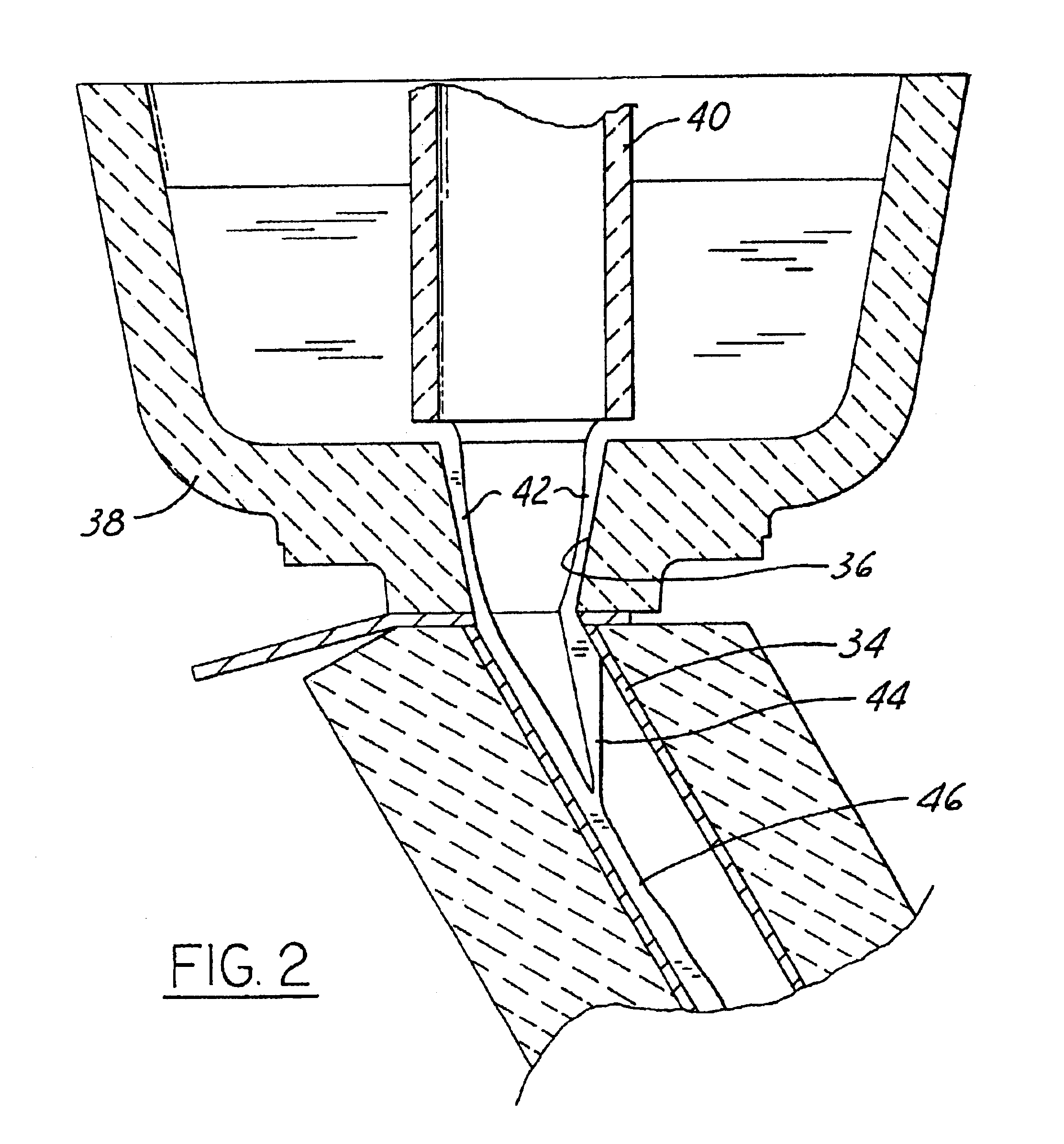
The drawings illustrate a system 10 for delivering a stream of cased glass. A first forehearth 12 delivers core glass to a bowl or spout 14 that has an opening 16 at the lower end thereof. Spout 14 is surrounded by a protective casing 18, preferably constructed of nonmagnetic material such as stainless steel. A spout tube 20 and a plunger 22 control delivery of core glass from spout 14 through opening 16 to and through one or more first orifices 24 carried by an upper orifice ring 26 beneath spout 14. A lower orifice ring 28 carries one or more second orifices 30 positioned beneath orifices 24 and axially aligned therewith. Orifice(s) 30 is surrounded by an annular chamber 32 formed between orifice rings 26, 28. Chamber 32 communicates with orifice(s) 30 by means of a lateral space or gap between orifices 24, 30. Annular chamber 32 is coupled by a delivery tube 34 to the opening 36 at the lower end of a casing glass spout 38. Spout 38 includes a delivery control spout tube 40, and i...


PUM

PropertyMeasurementUnit
pressureaaaaaaaaaa
gravityaaaaaaaaaa
volumeaaaaaaaaaa

Abstract

Apparatus for forming a cased glass stream having an inner core glass surrounded by an outer casing glass that includes a spout for delivering core glass from a first source through a first orifice. A second orifice is vertically spaced beneath and aligned with the first orifice, and is surrounded by an annular chamber that communicates with the second orifice through a gap between the first and second orifices. A tube delivers casing glass from the outlet opening of a casing glass spout to the annular chamber in such a way that glass flows by gravity through the orifices from the first and second sources to form the cased glass stream. A hollow tube within the casing glass spout is positioned with respect to the spout outlet opening for metering flow of casing glass through the outlet opening and delivery tube to the annular chamber surrounding the orifices. The interior of the hollow tube is coupled to a source of gas under pressure so as to maintain the tube interior, and the interior of the thin fall of casing glass through the spout outlet opening, at a pressure above ambient pressure surrounding the casing glass spout. This elevated gas pressure within the casing glass fall reverses the pressure differential between the interior and exterior of the spout outlet opening, so that any tendency for air to migrate through the refractory material surrounding the outlet opening and into the casing glass fall is eliminated.

Description

BACKGROUND AND OBJECTS OF THE INVENTIONThe present invention is directed to delivery of a glass stream for forming glass charges for glassware manufacture, and more particularly to a method and apparatus for delivering a so-called cased glass stream in which an inner or core glass is surrounded by an outer or casing glass.It has heretofore been proposed to provide a cased glass stream for forming glassware having layered wall segments. U.S. application Ser. Nos. 08 / 374,371 and 08 / 374,372 disclose techniques for delivering such a cased glass stream in which core glass from a first source is delivered through a first orifice. A second orifice is vertically spaced beneath and aligned with the first orifice, and is surrounded by an annular chamber that communicates with the second orifice through a gap between the first and second orifices. A heated tube delivers casing glass from a second glass source to the annular chamber that surrounds the second orifice. Glass flows by gravity thro...

Claims


Application Information

Patent Timeline
Patent Type & Authority Patents(United States)
IPC IPC(8): C03B7/084C03B7/00C03B7/08C03B7/082C03B7/09C03B17/00C03B17/02
CPCC03B7/08C03B7/084C03B7/082Y02P40/57
Inventor SCOTT, GARRETT L.FENSTERMACHER, JAMES E.
Owner OWENS-BROCKWAY GLASS CONTAINER INC
Why Eureka
Try Eureka