LED drive circuit for SCR dimming

a drive circuit and dimming technology, applied in the direction of static indicating devices, instruments, semiconductor lamp usage, etc., can solve the problems of low reliability, complex circuitry, and inability to achieve the purpose of illumination intensity adjustment, etc., to achieve good dimming effect, simple structure, and low cost

Active Publication Date: 2013-10-08
INVENTRONICS HANGZHOU
View PDF7 Cites 21 Cited by
  • Summary
  • Abstract
  • Description
  • Claims
  • Application Information

AI Technical Summary

Benefits of technology

[0011]The current controlling circuit processes the current detecting signal output (which is from the main circuit) and the controlling signal output (which is from the phase angle detecting circuit), and then outputs a current reference signal to the main circuit to control and adjust the current. Thereby, the main circuit can control the constant current and adjust the output current, which makes it possible to regulate the output current and adjust the illumination intensity of LED.
[0013]As the present invention adopts an LED drive circuit for SCR dimming, the phase angle detecting circuit and the controlling current circuit are ideal for all applications where an LED drive circuit for SCR dimming is employed. Whenever the external controller of the front-end dimming circuit sends out a dimming signal, the phase angle detecting circuit can detect the signal, and the current controlling circuit can adjust the output current according to the signal by the main circuit. The illumination intensity of LED will be adjusted by wide range, even with the small variation of the thyristor trigger phase angle in the external controller. The present invention features simple structure and low cost. It is able to generate good dimming effect without using complicated modems or wireless transmitters and receivers.

Problems solved by technology

Since the LED power supply is the AC / DC switching power supply with high efficiency and wide input voltage range, the traditional dimming mode such as controlling input voltage or phased angle, can not adjust the output voltage or current, and can not achieve the purpose of illumination intensity adjustment of LED.
But the shortages of this mode are expensive cost, complex circuitry, and low reliability (shown in FIG. 1).

Method used


Image

  • LED drive circuit for SCR dimming
  • LED drive circuit for SCR dimming
  • LED drive circuit for SCR dimming

Examples


first embodiment

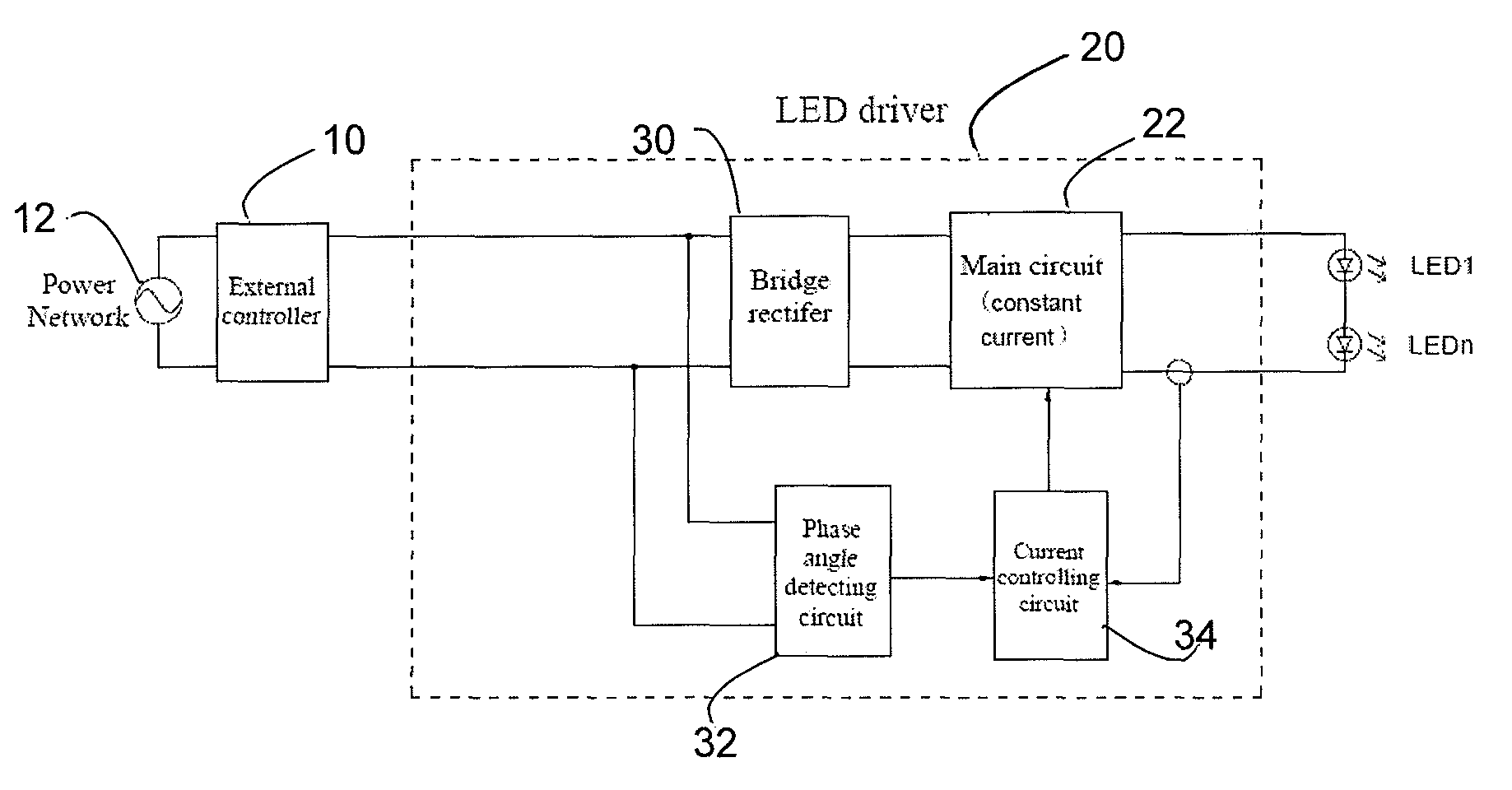
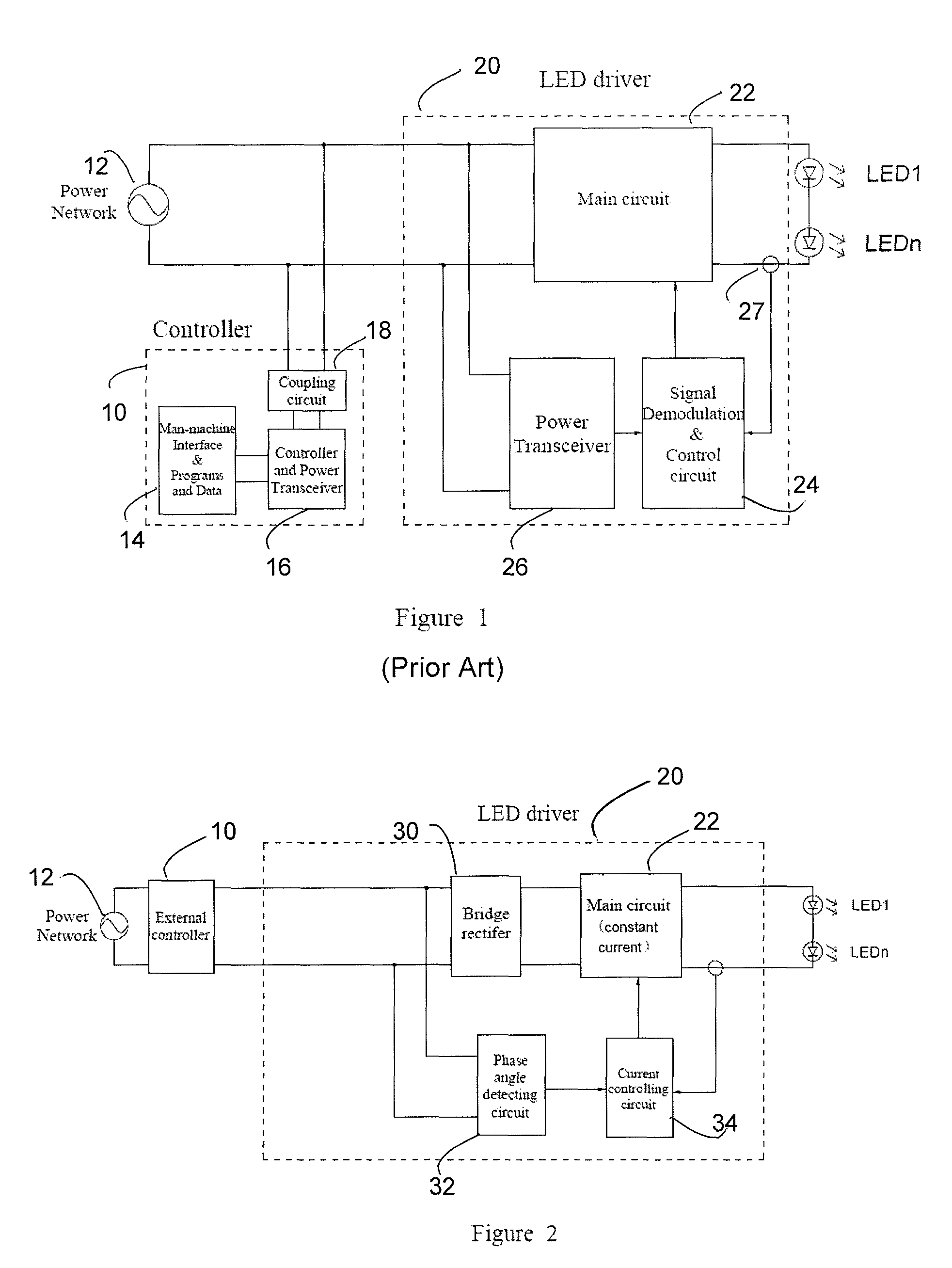
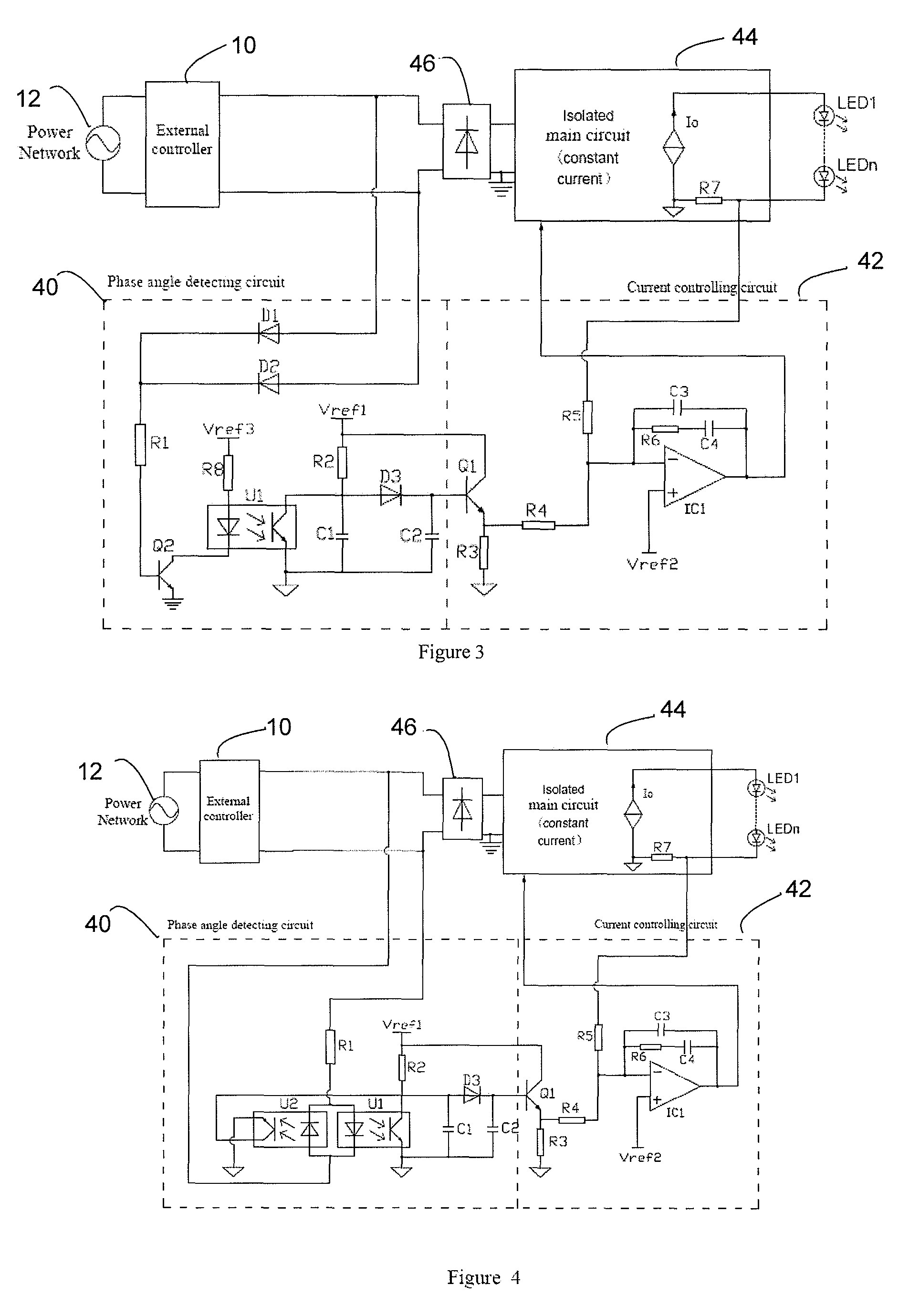
[0023]In FIG. 3, the first embodiment comprises an isolated phase angle detecting circuit and an isolated current controlling circuit, and an isolated main circuit with constant current output. The input of the external controller is the power network, and the output of the external controller is the input of the bridge rectifier and the phase angle detecting circuit.

[0024]The phase angle detecting circuit consists of resistor R1, resistor R2, resistor R8, capacitor C1, capacitor C2, diode D1, diode D2, diode D3, transistors Q2 and optocoupler U1.

[0025]The anodes of D1 and D2 are connected to the two output ends of the external controller respectively. The cathodes of D1 and D2, and one end of R1 are connected. The other end of R1 is connected to the base of Q2, while the emitter of Q2 is connected to the power ground. The cathode of the LED in U1 is connected to the collector of Q2, while the anode of U1 is connected to one end of R8. The other end of R8 is connected to the Vref3 e...

second embodiment

[0028]In FIG. 4, the second embodiment comprises an isolated phase angle detecting circuit, an isolated current controlling circuit, and an isolated main circuit with constant current output. The input of the external controller is power network, and the output of which is the input from the bridge rectifier and the phase angle detecting circuit.

[0029]The phase angle detecting circuit consists of resistor R1, resistor R2, capacitor C1, capacitor C2, diode D3, transistors Q1, optocoupler U1 and optocoupler U2.

[0030]A branch consists of the LEDs in U1 and U2 using an anti-parallel connection, and R1 in series. The two ends of the branch are connected to the two output ends of the external controller respectively. The collectors of the photistors in U1 and U2 are connected together, and then connected to the anode of D3, the ends of R2 and C1. The other end of R2 is connected to the Vref1 end of the second reference power supply. The emitters of photistors in U1 and U2 are connected to...

third embodiment

[0033]In FIG. 5, the third embodiment comprises an isolated phase angle detecting circuit and an isolated current controlling circuit use isolated circuit, and an isolated main circuit with constant current output. The input of the external controller is power network, and the output of the external controller is the input of the bridge rectifier and the phase angle detecting circuit.

[0034]The phase angle detecting circuit consists of resistor R1, resistor R2, capacitor C1, capacitor C2, diode D1, diode D2, diode D3, optocoupler U1.

[0035]The anodes of D1 and D2 are connected to the two output ends of the external controller respectively. The cathodes of D1 and D2, and one end of R1 are connected. The other end of R1 is connected to the anode of the LED in U1. The cathode of the LED in U1 is connected to the power ground. The collector of the photistor in U1 is connected to the anode of D3, one end each of R2 and C1. The other end of R2 is connected to the Vref1 end of the first refe...


PUM


Abstract

A LED drive circuit for SCR dimming including an external controller configured to receive AC voltage from a power network to convert the AC voltage to an AC voltage with a lacked phase by phase controlling the voltage through a thyristor, and a LED driver that includes a bridge rectifier configured to shape the AC voltage with the lacked phase output into a unidirectional pulse DC voltage, and a phase angle detecting circuit configured to shape the AC voltage signal output with lacked phase from the external controller into a saw-tooth wave pulse signal.

Description

CROSS-REFERENCE TO RELATED APPLICATIONS[0001]This application claims priority of Chinese Patent Application No. 200910100298.2 filed Jul. 6, 2009, which is incorporated herein by reference.TECHNICAL FIELD[0002]The present invention generally relates to an LED drive circuit for SCR dimming. More specifically, it relates to an LED drive circuit for SCR dimming by detecting phase angle and controlling current.BACKGROUND OF THE INVENTION[0003]With the increasing of energy consumption, the requirements on energy saving are getting higher and higher. The illumination consumption is an important part of the energy consumption. LED illumination, as an energy saving and green illumination, will replace the traditional gas discharge lamps and the incandescent lamps. LED has the advantages of long life, high luminous efficiency, and energy saving besides which, its simplicity in driving and controlling of the LED makes it easy and flexible to adjust the illumination intensity, which is particu...

Claims


Application Information

Patent Timeline
Patent Type & Authority Patents(United States)
IPC IPC(8): G09G3/32
CPCH05B33/0815H02M3/156H02M3/33507Y02B20/346Y02B20/347Y02B20/348Y02B20/383H05B45/385Y02B20/30
Inventor HUA, GUICHAOWU, XINKEYAO, XIAOLIGE, LIANGAN
Owner INVENTRONICS HANGZHOU
Why Eureka
Try Eureka