
Hybrid design of an anode disk structure for high prower X-ray tube configurations of the rotary-anode type

a technology of rotary anode and anode disk, which is applied in the direction of x-ray tube target materials, electric discharge tubes, reflex klystrons, etc., can solve the problems of long thermal “mass, high power x-ray anode, and refractory metals used as anode materials that do not provide high thermal conductivity, etc., to achieve high thermal conductivity, fast rotation, and high relative speed of focal tracks

Active Publication Date: 2013-10-08
KONINK PHILIPS ELECTRONICS NV
View PDF28 Cites 13 Cited by
  • Summary
  • Abstract
  • Description
  • Claims
  • Application Information

AI Technical Summary

Benefits of technology

The present invention solves the peak power limitation of conventional high power X-ray tubes by using a new design principle for the rotary anode disk. This new design allows for faster rotation of the anode and introduces a lightweight material with high thermal conductivity in the region adjacent to the focal track material. The extremely fast rotation is enabled by providing sections of the rotary anode disk made of anisotropic high specific strength materials which will be specifically adapted to the high stresses building up when the anode is operated. A X-ray system that is equipped with a high peak power anode according to the present invention will be capable of high speed image acquisition with high resolution and high coverage, which is needed for computed tomography of moving objects, for example in cardiac CT.

Problems solved by technology

A second disadvantage of conventional high power X-ray anodes, which has not been mentioned so far, lies in the fact that the refractory metals used as anode materials do not provide a high thermal conductivity.
Therefore, the thermal design no longer needs a large thermal “mass” but has to fully concentrate on quick heat distribution.

Method used


Image

  • Hybrid design of an anode disk structure for high prower X-ray tube configurations of the rotary-anode type
  • Hybrid design of an anode disk structure for high prower X-ray tube configurations of the rotary-anode type
  • Hybrid design of an anode disk structure for high prower X-ray tube configurations of the rotary-anode type

Examples


Embodiment Construction

[0068]In the following, the hybrid anode of the present invention will be explained in more detail with respect to special refinements and referring to the accompanying drawings.

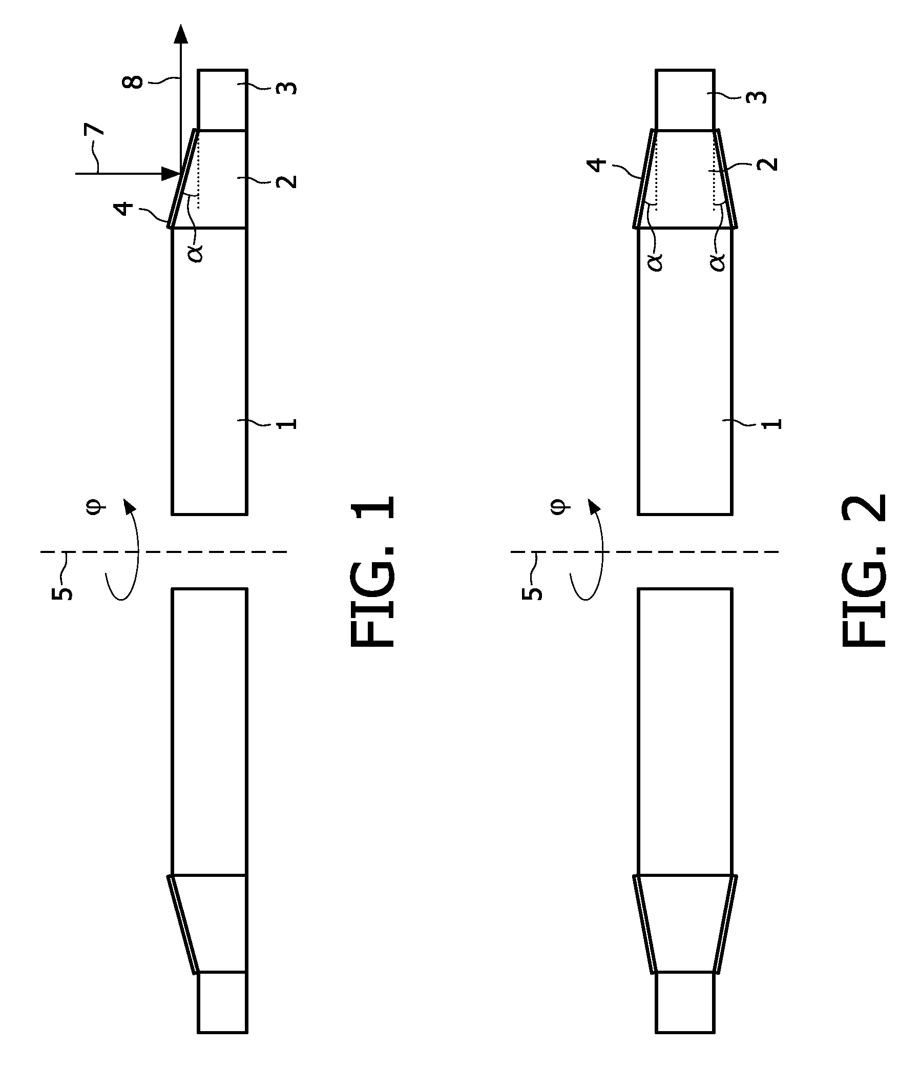
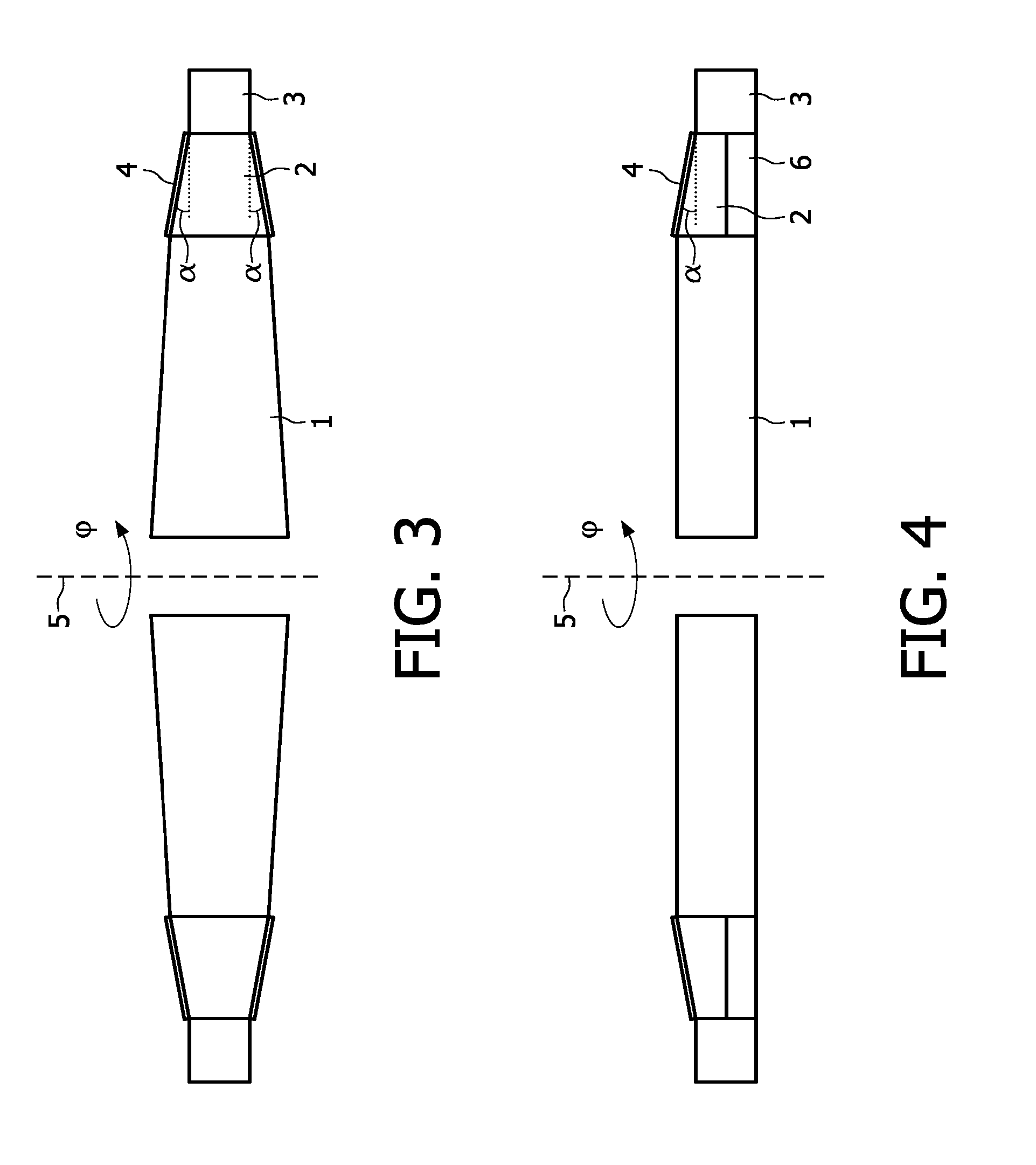
[0069]The basic exemplary embodiment of the present invention can be demonstrated by the design cross section of a rotary anode disk as depicted in FIG. 1. The proposed anode disk comprises two frame sections 1 and 3 made of anisotropic high specific strength materials with high mechanical strength and stability (“frame materials”, such as e.g. fiber-reinforced ceramic materials), that are specifically adapted to the high stresses building up when the anode disk is operated at extremely high rotational speed and extremely high short time peak power. Section 4 is a coating layer for the focal track, made of a material with high X-ray yield, e.g. containing a high percentage of tungsten (W) as a “track material”. Section 2 is made of a lightweight (not reinforced) material with high thermal conductivity (“ther...


PUM


Abstract

This invention relates to high power X-ray sources, in particular to those equipped with a rotating X-ray anode capable of delivering a higher short time peak power than conventional rotating x-ray anodes. This invention can overcome the thermal limitation of peak power by allowing fast rotation of the anode and by introducing a lightweight material with high thermal conductivity in the region adjacent to the focal track material. The fast rotation can be provided by using sections of the rotating anode disk made of anisotropic high specific strength materials with high thermal stability that can be specifically adapted to the high stresses of anode operation. Uses include high speed image acquisition for X-ray imaging, for example, of moving objects in real-time such as in medical radiography.

Description

[0001]The present invention is related to high power X-ray sources, in particular to X-ray tube configurations which are equipped with rotary anodes capable of delivering a much higher short time peak power than conventional rotary anodes according to the prior art which are for use in conventional X-ray sources. The herewith proposed design principle thereby aims at overcoming thermal limitation of peak power by allowing extremely fast rotation of the anode and by introducing a lightweight material with high thermal conductivity in the region adjacent to the focal track material. Such a high-speed rotary anode disk can advantageously be applied in X-ray tubes for material inspection or medical radiography, for X-ray imaging applications which are needed for acquiring image data of moving objects in real-time, such as e.g. in the scope of cardiac CT, or for any other X-ray imaging application that requires high-speed image data acquisition. The invention further refers to a high-spe...

Claims


Application Information

Patent Timeline
Patent Type & Authority Patents(United States)
IPC IPC(8): H01J25/26H01J35/00
CPCH01J35/108H01J2235/081H01J2235/088H01J2235/1006
Inventor LEWALTER, ASTRIDPIETIG, RAINERLANGKAMP, ALBERTRICHTER, HEIKOBEHNISCH, THOMASHUFENBACH, WERNERBEHLING, ROLF KARL OTTOBATHE, CHRISTOPH
Owner KONINK PHILIPS ELECTRONICS NV
Learn More