Method and apparatus for generating vapor at high rates

a high-rate, vapor-generating technology, applied in the direction of flash distillation, steam generation using steam absorption, combustion-air/fuel-air treatment, etc., can solve the problem of less responsive devices to changing vapor demands in the process, the overall physical size of the apparatus can increase, and the organic compound can decompose, etc. problem, to achieve the effect of high thermal conductivity and low thermal conductivity of one metal

Active Publication Date: 2013-10-08
MSP
View PDF13 Cites 17 Cited by
  • Summary
  • Abstract
  • Description
  • Claims
  • Application Information

AI Technical Summary

Benefits of technology

[0006]This disclosure also includes an apparatus for vaporizing liquids to form a vapor in a gas stream. The apparatus includes a structure that comprises a plurality of passageways for providing heat to vaporize the liquid in the gas stream, the passageways being disposed within a metal having a thermal conductivity of at least 5 times higher than that of stainless steel. A non-corrosive layer is disposed between the metal and the vaporizing liquid, the non-corrosive layer being chemically inert to the liquid being vaporized and the gas. The metal permits heat to be conducted rapidly throughout the structure to the liquid for vaporizing the liquid to form a gas / vapor mixture. The apparatus further comprises inlets for the gas and the liquid to flow into the plurality of passageways and an exit through which the gas / vapor mixture exits the apparatus.

Problems solved by technology

Some precursor chemicals such as metal-organic compounds can decompose at high temperatures to form undesirable by-products to cause process or equipment contamination.
Increasing the heat transfer surface area will generally cause the overall physical size of the apparatus to increase, thus making the device less responsive to changing vapor demands in the process.
As a result, the traditional approach to increasing vaporization rate is not suitable for all applications.

Method used


Image

  • Method and apparatus for generating vapor at high rates
  • Method and apparatus for generating vapor at high rates
  • Method and apparatus for generating vapor at high rates

Examples


Embodiment Construction

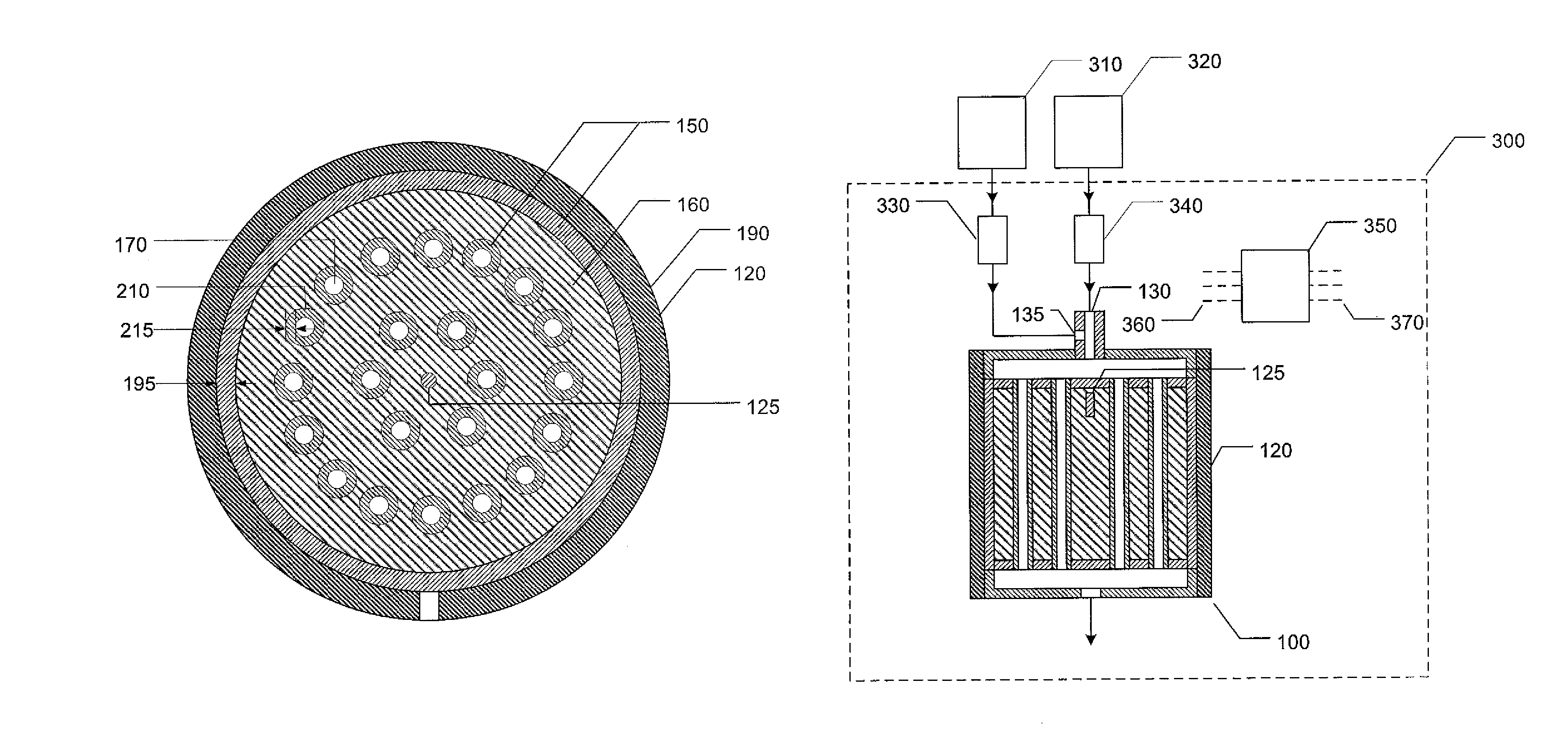
[0011]The present disclosure describes an approach to raising the vapor output and the capacity of a vapor generating apparatus without increasing its operating temperature or its physical size or both. The approach is particularly desirable for semiconductor device fabrication where a small compact device capable of generating vapor at a high rate is particularly advantageous.

[0012]For semiconductor device fabrication the precursor vapor generated by the vaporization apparatus must be pure and substantially free of particulate and gaseous contaminants. Material that can come into direct physical contact with the gas, vapor, and liquid flowing through the apparatus are referred to as “wetted surface.” Traditionally stainless steel is used because stainless steel can provide a clean and corrosion-resistant surface needed for the application.

[0013]While stainless steel is desirable from the point of view of vapor purity, its heat conducting or heat transfer properties are not particul...


PUM

PropertyMeasurementUnit
diameteraaaaaaaaaa
thermal conductivitiesaaaaaaaaaa
thermal conductivityaaaaaaaaaa

Abstract

The present disclosure relates to an apparatus and a method for vaporizing a liquid to form vapor preferably in a gas stream. The apparatus includes a composite metal structure, the structure comprising a plurality of passageways for providing heat to vaporize the liquid in the gas stream to form a gas / vapor mixture. A non-corrosive interface lies between the metal structure and the gas / vapor mixture, the interface being chemically inert to the gas / vapor mixture and the structure permitting heat to be conducted rapidly therethrough to vaporize the liquid. The apparatus further includes an inlet for the gas and an inlet for the liquid to be vaporized to flow into the plurality of passageways and an exit through which the gas / vapor mixture exits the apparatus.

Description

CROSS-REFERENCE TO RELATED APPLICATION[0001]The present application is based on and claims the benefit of U.S. provisional patent application Ser. No. 61 / 427,299, filed Dec. 27, 2010, the content of which is hereby incorporated by reference in its entirety.BACKGROUND OF THE DISCLOSURE[0002]The process of creating a vapor from a liquid usually involves heating the liquid to a sufficiently high temperature to form vapor. To generate vapor at a high rate, it is necessary to supply a substantial amount of energy in a short time to the liquid so that the needed vaporization energy can be provided. Traditionally, the output of a vapor generation apparatus can be increased by increasing the operating temperature to allow more heat to flow into the liquid to form vapor. Alternatively, a larger heat transfer surface area can be provided to increase the vapor generation rate. Both approaches have been used in the past and are well known to those skilled in the art of industrial equipment desi...

Claims


Application Information

Patent Timeline
Patent Type & Authority Patents(United States)
IPC IPC(8): F22B29/06F22B1/28B05B1/24F24H1/10F24H1/18A01G13/06A61M16/00A61H33/06B01D3/06A47J27/00A47J31/00
CPCB01D1/08A61M16/18F22B29/06F24H1/101F22B1/284A61M2205/3368A61M2205/50A61H33/065
Inventor DINH, THUCMA, YAMINLIU, BENJAMIN Y. H.
Owner MSP
Why Eureka
Try Eureka