Oil well blowout containment device

a technology for oil wells and containment devices, which is applied in the direction of sealing/packing, screw threaded joints, and borehole/well accessories. it can solve the problems of long time delay, no permanent deployment of these devices, and many disadvantages of known approaches

Inactive Publication Date: 2013-10-15
POWELL JOHN
View PDF49 Cites 28 Cited by
  • Summary
  • Abstract
  • Description
  • Claims
  • Application Information

AI Technical Summary

Benefits of technology

[0018]In accordance with yet another aspect of the invention, the blowout containment device is sufficiently well anchored to the sea bed and or the wellhead so as to not be displaced by the pressure of escaping oil and gas, or by currents or other disturbances.

Problems solved by technology

None of these devices are permanently deployed in advance of a blowout.
These known approaches all have many disadvantages as evidenced by the fact that none of them are in use.
Among the more serious drawbacks are difficult if not impossible tasks of positioning a conical, or other structure, over the venting oil and gas plume, failure to contain all or most of the oil, awkward deployment means which often requires specialized support equipment or vessels, obstruction of the wellhead, interference with normal drilling operations, a requirement that the containment apparatus be pre-positioned in a convenient location on land near the drill site or on the drilling platform, a long time delay between well blowout and spill containment, and the need for special training of crews for placement and or operation.

Method used


Image

  • Oil well blowout containment device
  • Oil well blowout containment device
  • Oil well blowout containment device

Examples


Embodiment Construction

[0030]The following description is of the best mode presently contemplated for carrying out the invention. This description is not to be taken in a limiting sense, but is made merely for the purpose of describing one or more preferred embodiments of the invention. The scope of the invention should be determined with reference to the claims.

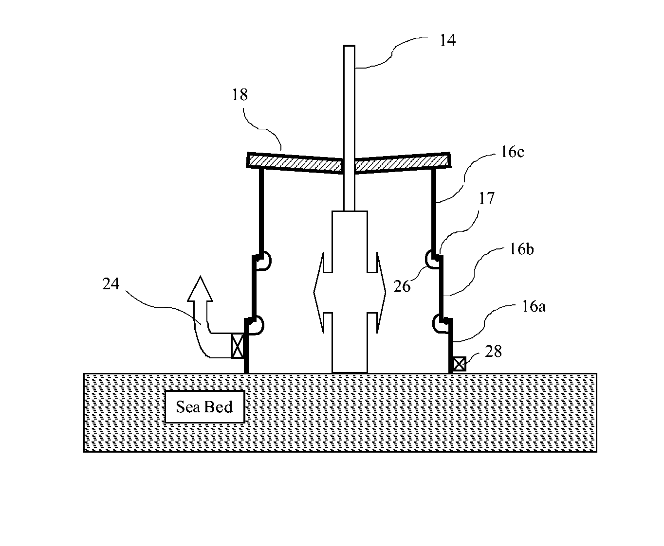
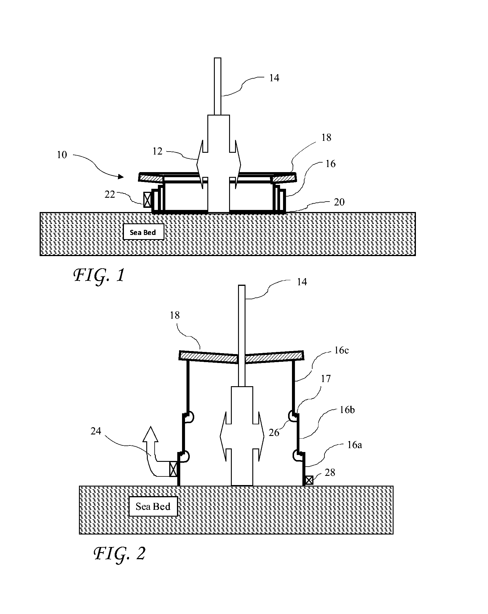
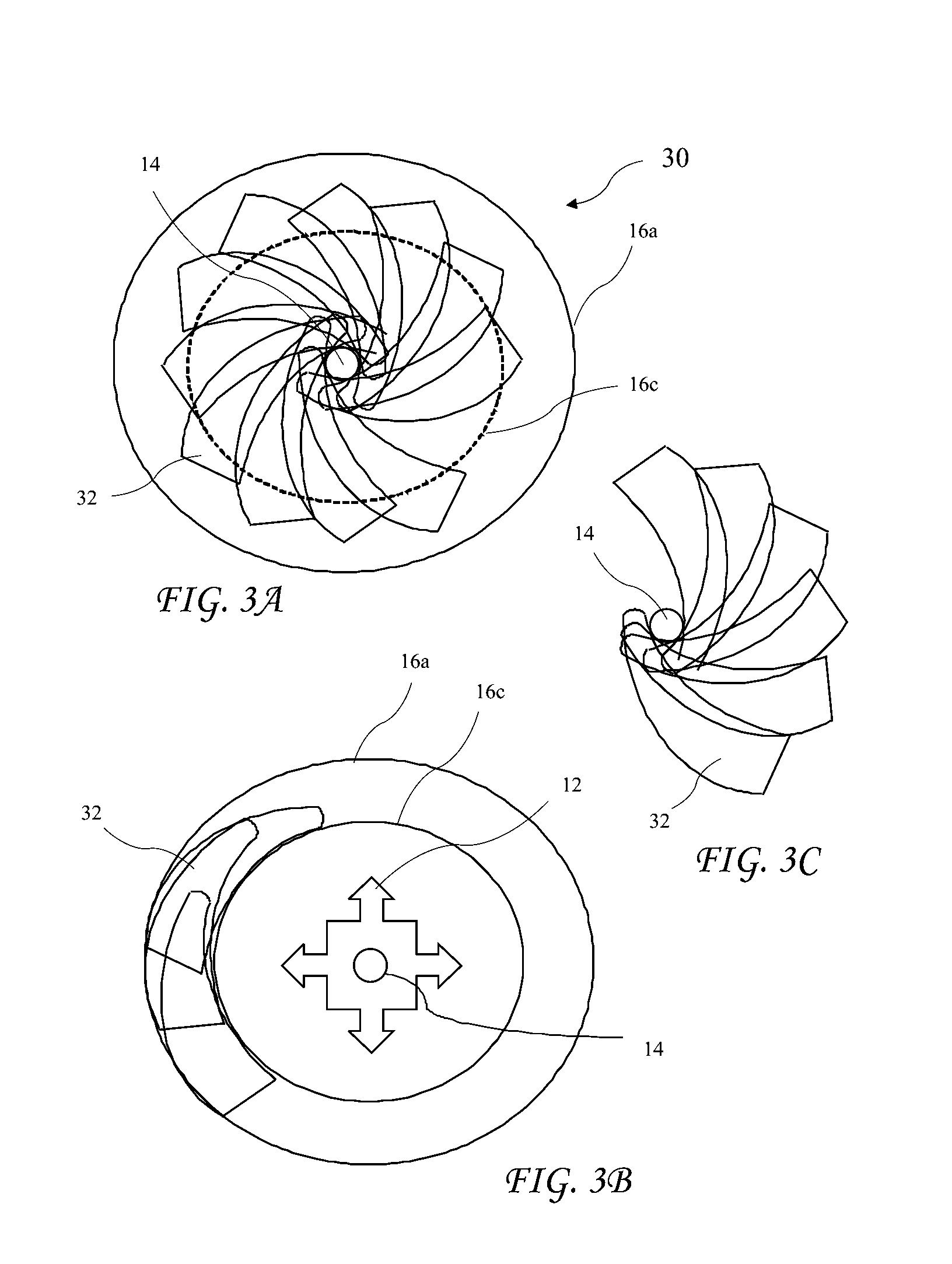
[0031]The world wide need for energy and the depletion of shore side reserves has driven oil drilling to ever deeper waters. Leaks or blowouts at any depth, even on land, can be very difficult to deal with, but the difficulty increases with increasing depth where drilling operations are at the leading edge of existing technology. The present invention is a blowout containment device for addressing subsea leaks.

[0032]The present invention includes telescoping steel cylinders that contain the flowing oil and gas, and direct it from ports through pipes to an existing manifold for transfer to tankers or undersea pipelines. Its function is to prevent o...


PUM


Abstract

A blowout containment system is permanently positioned on the wellhead. The blowout containment system is relatively inexpensive, is always available and in place, it does not interfere with normal drilling operations, will capture all of the oil and gas emitted by the blowout, does not require special or unique sea surface or underwater apparatus or vessels, does not have any operational requirements that are different than those which drilling crews normally use and are already familiar, and is activated the using actions are similar to those used by drilling crews for well drilling and completion.

Description

[0001]The present application claims the priority of U.S. Provisional Patent Application Ser. No. 61 / 353,064 filed Jun. 9, 2010 and U.S. Provisional Patent Application Ser. No. 61 / 380,178 filed Sep. 3, 2010, which applications are incorporated in their entirety herein by reference.BACKGROUND OF THE INVENTION[0002]The present invention relates to deep water oil well leak containment and in particular to a well-head collapsible enclosure for capturing escaping oil from a deep water well-head leak.[0003]Known devices to prevent uncontrolled release of oil into the ocean from underwater well blowouts fall into two categories: a) conical or umbrella-like structures that are lowered from a surface vessel over the blowout, and b) conical or dome-like structures that are permanently installed over the wellhead and that have some means of withdrawing collected oil and gas. None of these devices are permanently deployed in advance of a blowout.[0004]These known approaches all have many disadv...

Claims


Application Information

Patent Timeline
Patent Type & Authority Patents(United States)
IPC IPC(8): E21B43/01
CPCE21B43/0122
Inventor POWELL, JOHN
Owner POWELL JOHN
Why Eureka
Try Eureka