

Hydrogen system and method for starting up a hydrogen system
- Summary
- Abstract
- Description
- Claims
- Application Information
AI Technical Summary
Benefits of technology
Problems solved by technology
Method used
Image

Examples
first embodiment
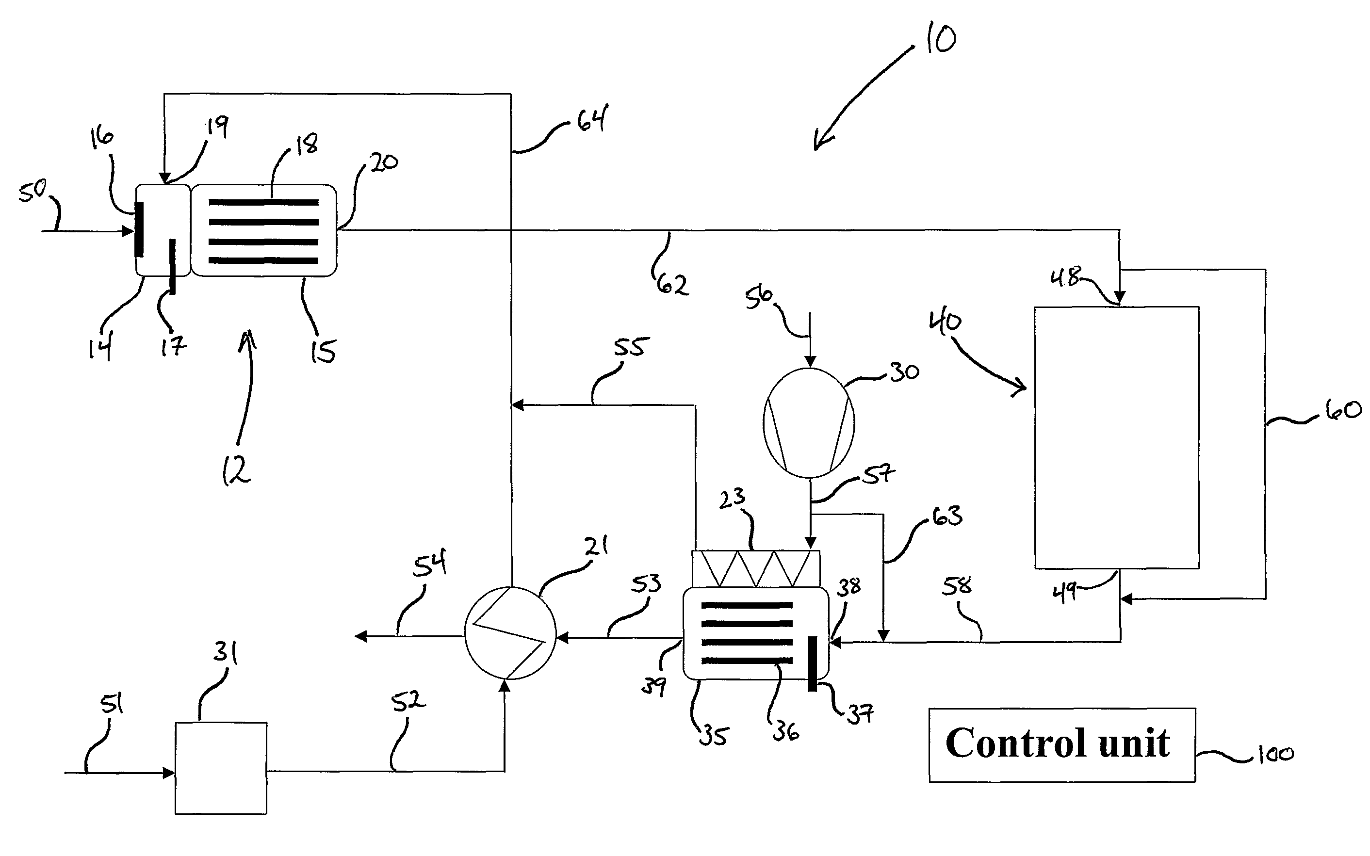
[0077]FIG. 1 schematically shows the present invention where the hydrogen system 10 comprises a reformer 12 where reforming process takes place.
[0078]The reformer 12 comprises a mixing space 14 and a reformer space 15. The mixing space and the reformer space may be formed as two separate units or compartments, as indicated on FIG. 1, but then there must be arranged for fluids to flow from the mixing space 14 to the reformer space 15. Alternatively, the reformer is formed in a single unit or compartment wherein the mixing space 14 and the reformer space 15 occupy different spaces in the unit.
[0079]The mixing space 14 further comprises vaporizer 16 for vaporizing the liquid hydrocarbon fuel which is fed through the fluid line 50 to the vaporizer 16, through the vaporizer, which vaporizes the liquid hydrocarbon fuel as the fuel passes through the vaporizer 16. In the mixing space 14, the vaporized fuel is mixed with air or a mix of air and steam. The vaporized fuel is mixed with air in...
second embodiment
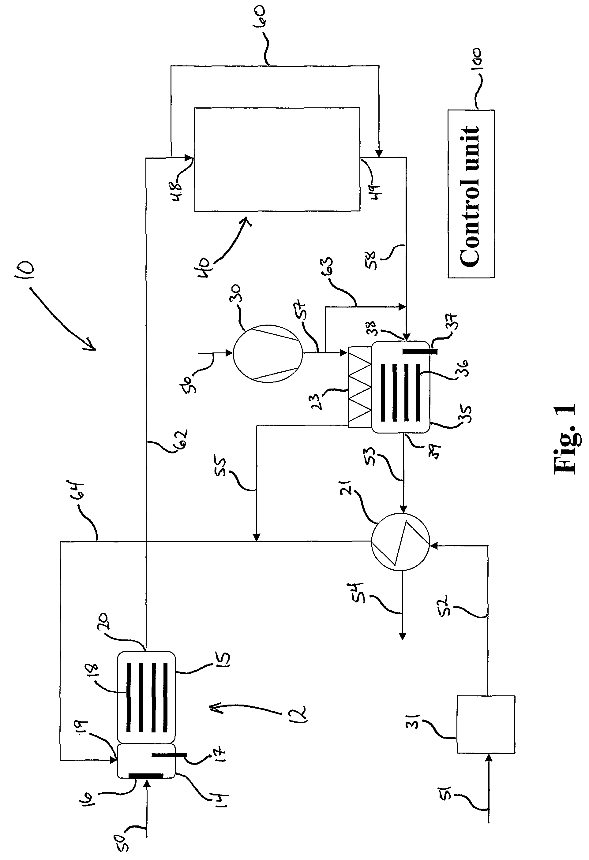
[0093]In FIG. 2 the invention is shown. This embodiment is basically the same as the embodiment shown in FIG. 1 and the common features of the two embodiments will not be discussed again.
[0094]The difference between the embodiments of the present invention shown in FIGS. 1 and 2 is that the embodiment shown in FIG. 2 is provided with a second heat exchanger 22. The second heat exchanger is connected to the first heat exchanger through the fluid line 68 and further to the reformer 12 through fluid line 69. The steam produced in the first heat exchanger 21 is fed through the fluid line 68, in which it is mixed with air from fluid line 55, further through the second heat exchanger 22 and then to the reformer 12. The second heat exchanger 22 is also connected to the outlet 20 of the reformer through fluid line 66 and to the inlet 48 of the hydrogen consumer 40 through fluid line 67. The reformate gas produced in the reformer 12 is fed through the fluid line 66 to and through, the second...
third embodiment
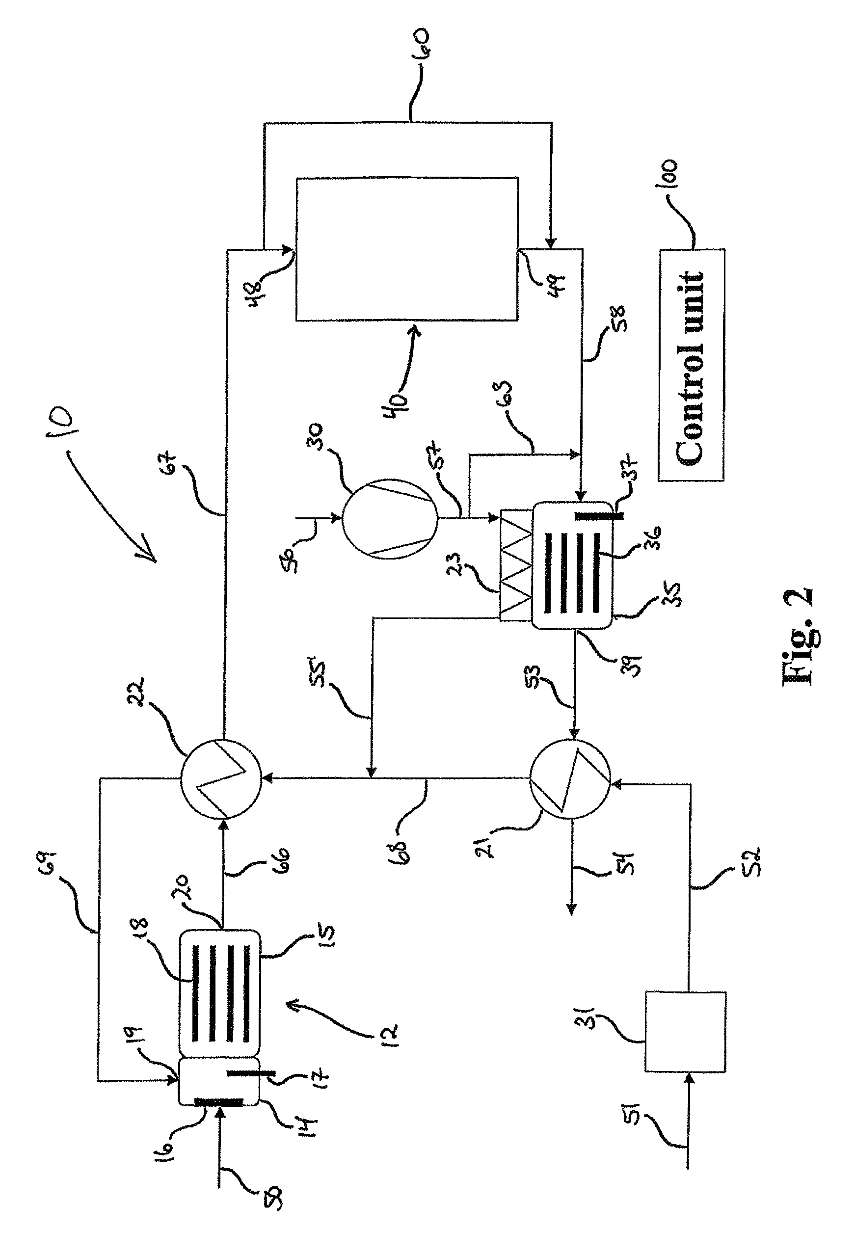
[0097]the invention is shown on FIG. 3. This embodiment also has many similarities with the two embodiments of the invention already described. Generally, the features which are common to the three embodiments will not be discussed again.
[0098]The third embodiment of the hydrogen system 10, shown on FIG. 3, comprises, in addition to the features of the second embodiment, a water shift reactor 25, a fourth heat exchanger 24 and fan 32 which supplies air to the hydrogen consumer 40 which in this embodiment comprises a fuel cell, preferably a HT-PEM fuel cell 41.
[0099]When the hydrogen consumer 40 comprises a HT-PEM fuel cell, it may be necessary to keep the amount of carbon monoxide present in the reformate gas which is fed into the HT-PEM fuel cell below a certain level in order not to poison the membrane of the HT-PEM fuel cell. This is done by providing the water shift reactor 25 which removes enough carbon monoxide present in the reformate gas from the reformer 12 to keep the leve...
PUM
 Abstract
Description
Claims
Application Information