Remote combustion deposition burner and/or related methods

a burner and combustion technology, applied in the direction of combustion types, lighting and heating apparatuses, solid-state diffusion coatings, etc., can solve the problems of significant increase in substrate temperature, stress change in glass, and limited control mechanisms, so as to reduce fuel consumption, reduce heat flux to the substrate, and enhance reaction control

Inactive Publication Date: 2013-10-22
GUARDIAN GLASS LLC
View PDF16 Cites 0 Cited by
  • Summary
  • Abstract
  • Description
  • Claims
  • Application Information

AI Technical Summary

Benefits of technology

[0006]There are several advantages of combustion CVD over traditional pyrolytic deposition techniques (such as CVD, spray and sol-gel, etc.). One advantage is that the energy required for the deposition is provided by the flame. A benefit of this feature is that the substrate typically does not need to be heated to temperatures required to activate the conversion of the precursor to the deposited material (e.g., a metal oxide). Also, a curing step (typically required for spray and sol-gel techniques) typically is not required. Another advantage is that combustion CVD techniques do not necessarily require volatile precursors. If a solution of the precursor can be atomized / nebulized sufficiently (e.g., to produce droplets and / or particles of sufficiently small size), the atomized solution will behave essentially as a gas and can be transferred to the flame without requiring an appreciable vapor pressure from the precursor of interest.
[0017]Some techniques use a combustion deposition device in which the precursor is delivered independent of the flame. This approach is described in, for example, U.S. Publication No. 2005 / 0061036, the entire contents of which is hereby incorporated herein by reference. However, these products appear to involve substantially different burner designs and also appear to be limited to the deposition of optical preforms. Current remote CCVD (R-CCVD) efforts, such as those performed by Innovent, for example, aim for greater control over reaction conditions by delivering the precursor externally to the flame. The proposed design of certain example embodiments (described in greater detail below) improves upon this approach by utilizing IR burner technology. This provides for a substantially less turbulent reaction zone, which may provide improved coating uniformity and repeatability. Within an IR burner, combustion takes place primarily within the body of the burner before the combustion gasses exit the refractory faceplate. Additionally, IR burners of the type described herein consume less fuel and deliver heat over a substantially more planar area than conventional linear “ribbon” burners. The substantially lower flow rate of combustion gases per unit area and refractory faceplate provide for substantially less turbulent conditions at the exit of the burner, which may provide for a more controllable reaction zone, leading to improved coating uniformity and deposition repeatability. Additionally, the refractory faceplate also serves as an upper bound for the precursor containing carrier gas that is inserted between the faceplate and the glass. This has the effect of controlling the turbulence of the gasses within the reaction zone leading to greater control. It may also be possible to “tune” the primary wavelengths of IR radiation emitted from the refractory faceplate to favor certain reaction conditions through control of the combustion conditions. Indeed, the IR energy emitted from the refractory faceplate may be sufficient to promote precursor reaction and film growth. Of course, the use of an IR burner also may carry some or all of the advantages described in application Ser. No. 12 / 000,784 (the entire contents of which is hereby incorporated herein by reference).
[0019]In certain example embodiments, a method of applying a coating to a substrate using combustion deposition is provided. A substrate having at least one surface to be coated is provided. A reagent (and optionally, a carrier medium) is selected, and if a carrier medium is selected, the reagent and the carrier medium are mixed together to form a reagent mixture, with the reagent being selected such that at least a portion of the reagent forms the coating. A precursor to be combusted with the reagent (or reagent mixture) is introduced, with the precursor including silicon. Using at least one infrared burner, at least a portion of the reagent (or reagent mixture) and the precursor are combusted to form a combusted material. The substrate is provided in an area so that the substrate is heated sufficiently to allow the combusted material to form the coating, directly or indirectly, on the substrate. The deposited coating comprises silicon oxide. The coating increases visible transmission of the glass substrate by at least about 1.7%.
[0022]In addition to these example embodiments, the inventor of the instant application also has been able to create a remote combustion deposition burner in which the precursor is delivered along with a carrier gas stream to the reaction zone external to the flame. In brief, a distribution device provided in connection with certain example burner configurations provides an at least initially substantially laminar flow of a gaseous stream comprising the precursor and the carrier gas, which ultimately is substantially uniform across the coat zone. Thus, certain example embodiments realize at least some the benefits of infrared (IR) burner deposition described herein, as well as advantages more specific to using remote combustion deposition techniques including, for example, reduced heat flux to the substrate, reduced fuel consumption, possible enhanced reaction control and ability to use moisture / oxygen sensitive precursors to deposit coatings (as precursor can be delivered in inert carrier gas), and / or the like.

Problems solved by technology

Unfortunately, however, these control mechanisms can be fairly limited, depending on the particular application.
Unfortunately, the heat flux produced during combustion deposition creates a significant increase in substrate temperature.
The substrate temperature extremes and resultant thermal gradient experienced by the glass during deposition leads to stress changes in the glass.
This phenomenon, in turn, has resulted in spontaneous glass fracture during coating, in post-coating cooling, and / or in subsequent deposition of the same film on the opposite side of the lite.
Additionally, the glass experiences bowing, which ultimately leads to coating uniformity issues.
However, these products appear to involve substantially different burner designs and also appear to be limited to the deposition of optical preforms.

Method used


Image

  • Remote combustion deposition burner and/or related methods
  • Remote combustion deposition burner and/or related methods
  • Remote combustion deposition burner and/or related methods

Examples


Embodiment Construction

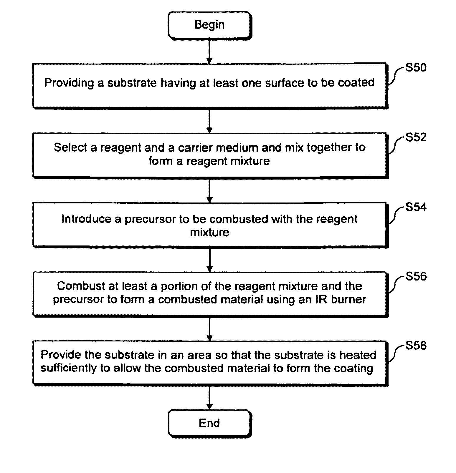
[0036]In certain example embodiments of this invention, a method of forming a coating on a glass substrate using combustion deposition is provided. A glass substrate having at least one surface to be coated is provided. A reagent and an optional carrier medium are selected, and the reagent and the carrier medium are mixed together to form a reagent mixture. The reagent is selected such that at least a portion of the reagent is used in forming the coating. A precursor to be combusted with the reagent mixture is introduced. Using at least one infrared burner, at least a portion of the reagent mixture and the precursor are combusted to form a combusted material, with the combusted material comprising non-vaporized material. The glass substrate is provided in an area so that the glass substrate is heated sufficiently to allow the combusted material to form the coating, directly or indirectly, on the glass substrate. The coating may be applied in a substantially uniform manner (e.g., acr...


PUM

PropertyMeasurementUnit
distanceaaaaaaaaaa
wavelengthsaaaaaaaaaa
distanceaaaaaaaaaa

Abstract

Certain example embodiments relate to a burner for use in combustion deposition depositing a coating on a substrate. An infrared (IR) burner generates radiant energy in an area between the burner and the substrate. A delivery device (1) provides a stream comprising a substantially vaporized precursor and a carrier gas from a location remote from the radiant energy generated by the IR burner, and (2) causes the stream to flow between the substrate and the IR burner. The stream is substantially laminar when exiting the delivery device. The radiant energy is sufficient to cause the precursor in the stream to be combusted and to heat the substrate to allow at least a portion of the combusted precursor to form the coating, directly or indirectly, on the substrate. The burners of certain example embodiments may be used, for example, to combustion deposition deposit metal oxide coatings onto glass substrates.

Description

CROSS-REFERENCE TO RELATED APPLICATION[0001]This application is a continuation-in-part of application Ser. No. 12 / 000,784 filed Dec. 17, 2007 now U.S. Pat. No. 8,440,256, the entire contents of which is hereby incorporated herein by reference.FIELD OF THE INVENTION[0002]Certain example embodiments of this invention relate to the deposition of thin film coatings onto substrates via remote combustion deposition. More particularly, certain example embodiments relate to a burner design that enables a precursor to be delivered along with a carrier gas stream to the reaction zone external to or remote from the flame(s). In certain example embodiments, a distribution device provides an at least initially substantially laminar flow of a gaseous stream comprising the precursor and the carrier gas, which ultimately is substantially uniform across the coat zone.BACKGROUND AND SUMMARY OF EXAMPLE EMBODIMENTS OF THE INVENTION[0003]Reagent concentration, temperature, and residence time are known f...

Claims


Application Information

Patent Timeline
Patent Type & Authority Patents(United States)
IPC IPC(8): C23C8/00B05D5/06
CPCC03C17/002C03C17/245C23C16/402C23C16/453C23C16/45504F23D14/12F23D14/125F23D14/14F23D14/56F23D99/003C03C2217/732C03C2218/15F23D91/02
Inventor MCLEAN, DAVID D.
Owner GUARDIAN GLASS LLC
Why Eureka
Try Eureka