
Method and apparatus for synthesizing carbon nanotubes using ultrasonic evaporation

a carbon nanotube and ultrasonic evaporation technology, applied in the direction of carbonsing rags, chemistry apparatus and processes, chemical/physical/physico-chemical processes, etc., can solve the problems of inconvenient mass production of carbon nanotubes, low purity of obtained products, and insufficient synthesis of carbon nanotubes

Inactive Publication Date: 2011-02-03
KOREA INST OF ENERGY RES
View PDF6 Cites 0 Cited by
  • Summary
  • Abstract
  • Description
  • Claims
  • Application Information

AI Technical Summary

Benefits of technology

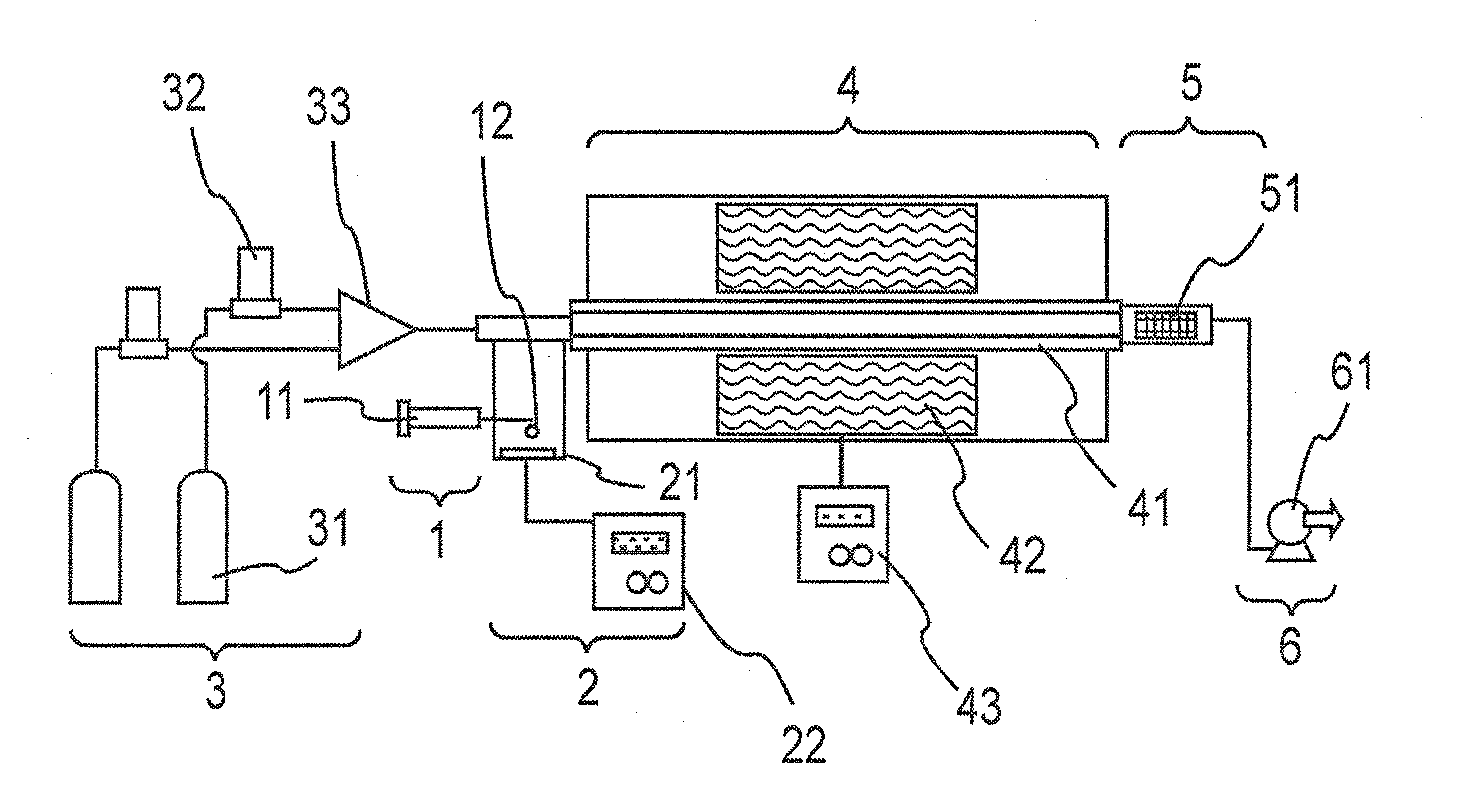
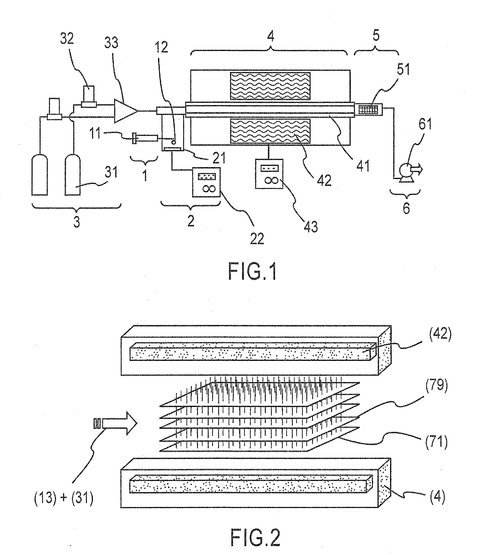
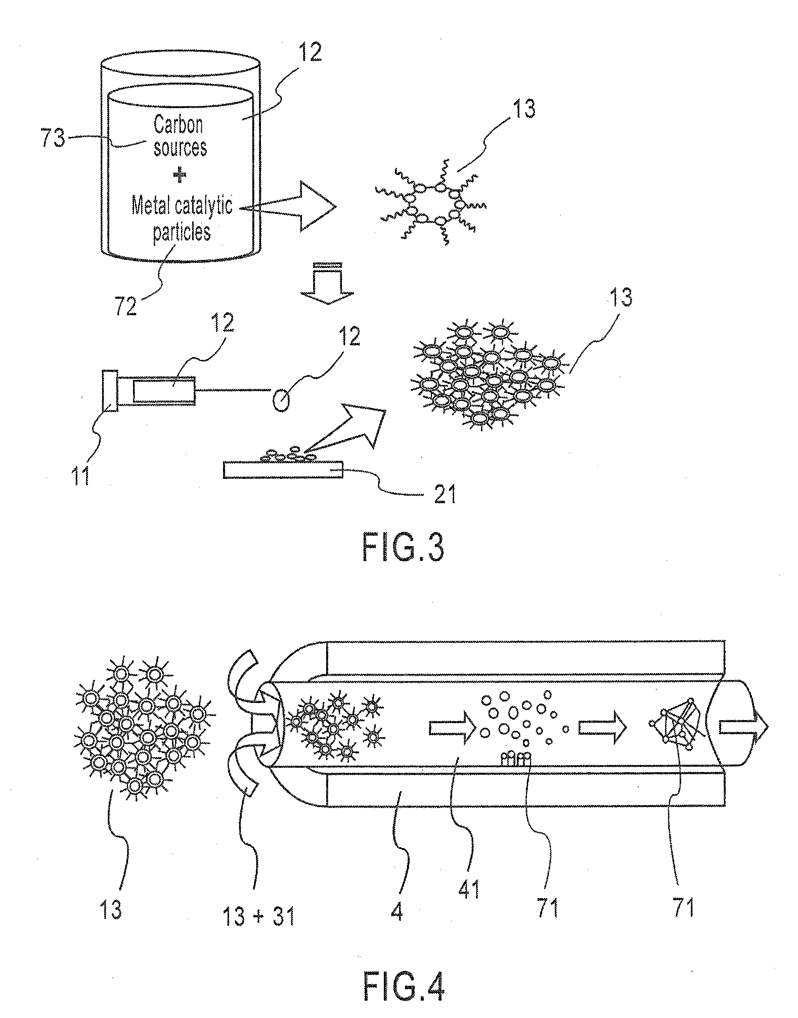
The present invention provides an apparatus and method for synthesizing carbon nanotubes using a liquid metal catalyst mixture, which can produce a large amount of carbon nanotubes uniformly and easily. The apparatus includes a fuel supply unit for supplying the liquid metal catalyst mixture, an evaporation unit for atomizing the mixture, a carrier gas supply unit for transferring the atomized precursors to a reactor, a reaction unit for mass production of carbon nanotubes, a filtering unit for filtering the synthesized carbon nanotubes, and a vacuum generation unit for removing oxygen from the reactor. The method includes supplying a liquid metal catalyst mixture, producing precursors with a uniform size, pyrolyzing the precursors to carbon atoms, and adsorbing and diffusing the carbon atoms onto metal catalytic particles to form carbon nanotubes. The invention allows for easy and efficient synthesis of carbon nanotubes on large area substrates.

Problems solved by technology

In this method, although high-quality carbon nanotubes can be synthesized, there are disadvantages in that the purity of the obtained products is low and in that it is not suitable for the mass production of carbon nanotubes.
The laser ablation method has advantages in that the produced carbon nanotubes are relatively straight and have high quality, but has disadvantages in that the energy consumption of apparatus is necessary for synthesis.
Further, these methods have disadvantages in that additional purification are required in order to realize high purity after the synthesis of carbon nanotubes, and in that it is difficult to control the structures of the carbon nanotubes and grow the carbon nanotubes vertically.
However, this method has disadvantages in that the evaporation of metal catalytic particles and carbon sources, having different boiling points from each other, in a vessel can be influenced by the heating condition for evaporation, and in that it is difficult to maintain the amount of precursor constant because the amount of mixture in the vessel changes with the passage of time.
However, these methods have problems in that the initial investment costs are high because the apparatuses used in these methods are relatively expensive, and in that control systems are complicated.

Method used


Image

  • Method and apparatus for synthesizing carbon nanotubes using ultrasonic evaporation
  • Method and apparatus for synthesizing carbon nanotubes using ultrasonic evaporation
  • Method and apparatus for synthesizing carbon nanotubes using ultrasonic evaporation

Examples


example 1

[0085]An apparatus for synthesizing carbon nanotubes was disposed as shown in FIG. 1, and then an experiment thereon was carried out as shown in FIG. 7. FIG. 7 is graphs showing an example of the synthesis of carbon nanotubes and the control of the structure thereof depending on the synthesis time in a thermal pyrolysis system using an ultrasonic evaporation method according to the present invention.

[0086]The experiment was carried out under the condition that the reaction unit 4, shown in FIG. 1, was maintained at a temperature of 850° C., the concentrations of metal catalytic particles 72 included in liquid carbon sources 73 were 6.5 mol % in all experiments, the supply rate of the liquid metal catalyst mixture 12 was maintained at a rate of 5 ml / hr through a syringe pump 11, and the synthesis times of the carbon nanotubes 71 were 30 min, 60 min, 90 min and 120 min, respectively. The results of the experiments are shown in FIG. 7. The liquid metal catalyst mixture 12 supplied thro...

example 2

[0089]An apparatus for synthesizing carbon nanotubes was disposed as shown in FIGS. 1 and 2, and then an experiment thereon was carried out as shown in FIG. 8. The experiment was carried out under the condition that the temperature in the reaction unit 4, shown in FIG. 1, was maintained at a temperature of 800° C., the concentrations of metal catalytic particles 72 included in liquid carbon sources 73 were 6.5 mol % in experiments, the supply rate of a liquid metal catalyst mixture 12 was maintained at a rate of 500 ml / hr through a general quantitative pump without using a syringe pump 11, and the synthesis time of the carbon nanotubes 71 was 30 min. The results of the experiments are shown in FIG. 8. Since the liquid metal catalyst mixture 12 supplied through the general quantitative pump was supplied through a tube having a diameter of 1 / 16 inches and was then continuously supplied to a vibration plate, the vibration plate was continuously operated in an ON state. Maximum power co...

example 3

[0090]An apparatus for synthesizing carbon nanotubes was disposed as shown in FIG. 1, and then an experiment thereon was carried out as shown in FIG. 9. FIG. 9 is graphs showing an example of the synthesis of carbon nanotubes and the control of the structure thereof depending on reactor temperature in a thermal pyrolysis system using an ultrasonic evaporation method according to the present invention. As shown in FIG. 9, the average diameters of samples were evaluated according to the experimental results measured under the condition that the temperatures of reaction unit 4, shown in FIG. 1, were 700° C., 800° C., 900° C. and 1000° C., respectively.

[0091]The carbon nanotubes 71 were grown under the condition that the concentrations of metal catalyst particles 72 included in liquid carbon sources 73 were 6.5 mol % in all experiments, the supply rate of the liquid metal catalyst mixture 12 was maintained at a rate of 5 ml / hr using a syringe pump 11, and the synthesis time of the carbo...


PUM

PropertyMeasurementUnit
temperatureaaaaaaaaaa
inner diameteraaaaaaaaaa
temperatureaaaaaaaaaa

Abstract

Disclosed herein is an apparatus and method for synthesizing carbon nanotubes, including a fuel supply unit for supplying a large amount of liquid metal catalyst mixture using a syringe pump for quantitatively supplying a liquid metal catalyst mixture, mixed with hydrocarbon-based liquid carbon sources such as xylene, toluene, benzene and the like, and metal catalytic particles, such as iron, nickel, cobalt, molybdenum and the like, and a general liquid pump for supplying a liquid metal catalyst mixture depending on the amount thereof; an evaporation unit for evaporating and atomizing the liquid metal catalyst mixture supplied from the fuel supply unit into precursors having a uniform size on the nanometer scale; a carrier gas supply unit for transferring particles atomized in the evaporation unit to a reactor and transferring carrier gas, having an influence on the synthesis of carbon nanotubes, to the reactor; a horizontally oriented reaction unit for synthesizing carbon nanotubes in large quantities using the carrier gas supplied from the carrier gas supply unit and the precursors formed in the evaporation unit; a filtering unit comprising a filter for filtering residual particles among the atomized particles synthesized into carbon nanotubes in the horizontally oriented reaction unit and some of the carbon nanotubes synthesized in the vapor phase; and a vacuum generation unit comprising a vacuum pump configured to be connected with the filtering unit, decrease pressure in the reactor, and remove oxygen remaining in the reactor, or a continuous collection unit in the case where the apparatus includes a vertical type reaction unit.

Description

CROSS-REFERENCE TO RELATED APPLICATIONS [0001]This is a Divisional application which claims the benefit of pending U.S. patent application Ser. No. 11 / 723,785, filed on Mar. 22, 2007, and claims priority of Korean Patent Application No. 0027795 / 2006, filed on Mar. 28, 2006, and Korean Patent Application No. 0013553 / 2007, filed on Feb. 9, 2007. The disclosures of the prior applications are hereby incorporated herein in their entirety by reference.BACKGROUND OF THE INVENTION [0002]1. Field of the Invention[0003]The present invention relates to a method and apparatus for synthesizing carbon nanotubes using ultrasonic evaporation and, more particularly, to a method and apparatus for synthesizing carbon nanotubes, in which precursors having uniform sizes, composed of metal catalytic particles, carbon atoms and hydrogen atoms, are produced, either in large quantities or continuously, by instantaneously evaporating and atomizing a liquid metal catalyst mixture including hydrocarbon liquid ...

Claims


Application Information

Patent Timeline
Patent Type & Authority Applications(United States)
IPC IPC(8): D01F9/12B82Y40/00
CPCB01J19/10B01J2219/00087C01B31/0233B82Y40/00B82Y30/00C01B32/162
Inventor JEONG, NAM-JOSEO, YONG-SEOG
Owner KOREA INST OF ENERGY RES
Learn More