
Engine controlling apparatus

Active Publication Date: 2013-10-29
MITSUBISHI MOTORS CORP
View PDF16 Cites 0 Cited by
  • Summary
  • Abstract
  • Description
  • Claims
  • Application Information

AI Technical Summary

Benefits of technology

The present invention aims to improve the accuracy of torque-based control in an engine with a simple configuration. It aims to enhance the accuracy of torque calculation and implement a high degree of accuracy in response to demand torque. This is achieved by controlling the ignition timing of the engine based on actual torque and the first target torque.

Problems solved by technology

Accordingly, there is a subject that it is difficult to enhance the calculation accuracy of a high-response demand torque unless the calculation accuracy of the low-response demand torque is secured.
However, since the low-response demand torque is calculated based on a driver demand torque and an external demand torque and the actual torque is not taken into consideration, there is a limitation to assurance of calculation accuracy.

Method used


Image

  • Engine controlling apparatus
  • Engine controlling apparatus
  • Engine controlling apparatus

Examples


Embodiment Construction

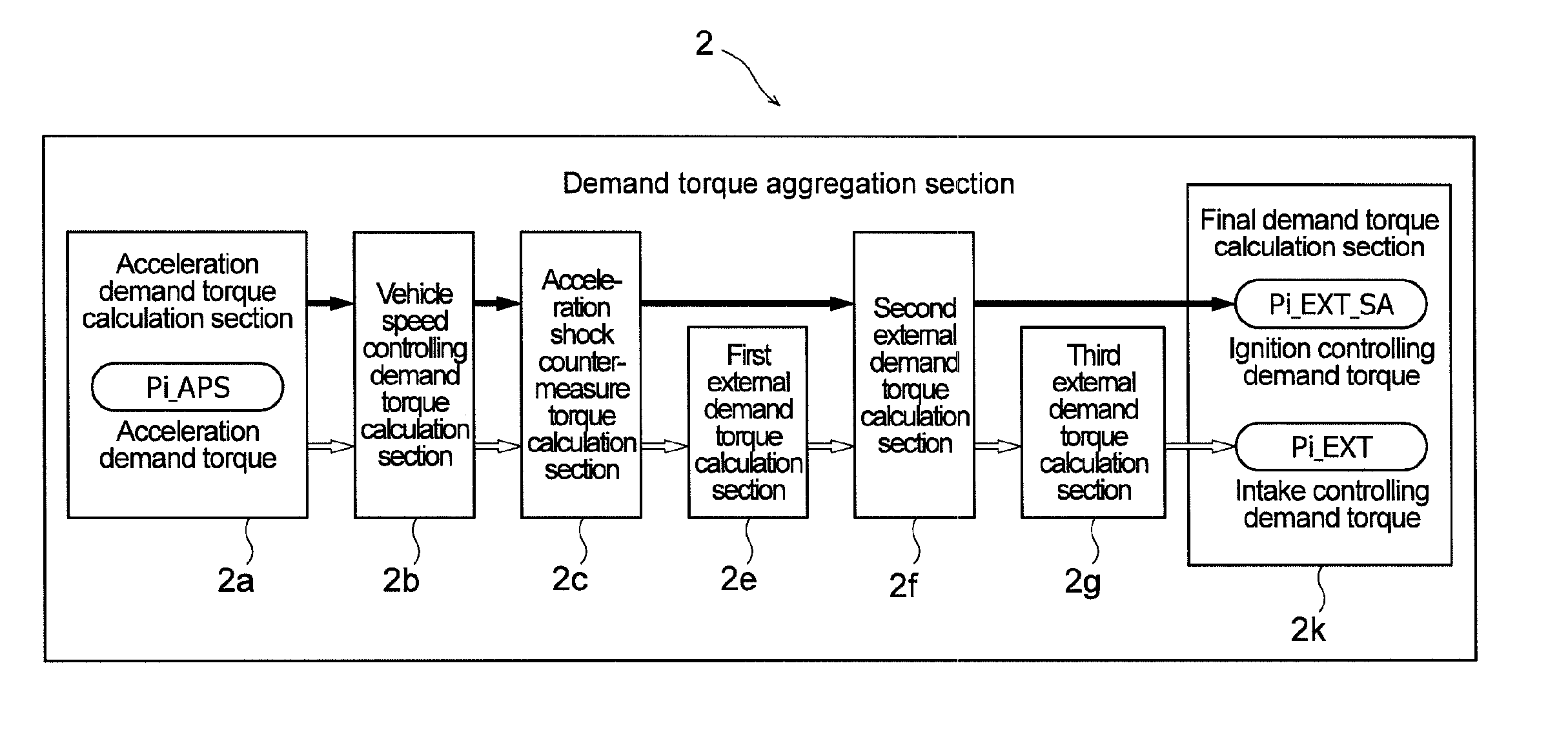
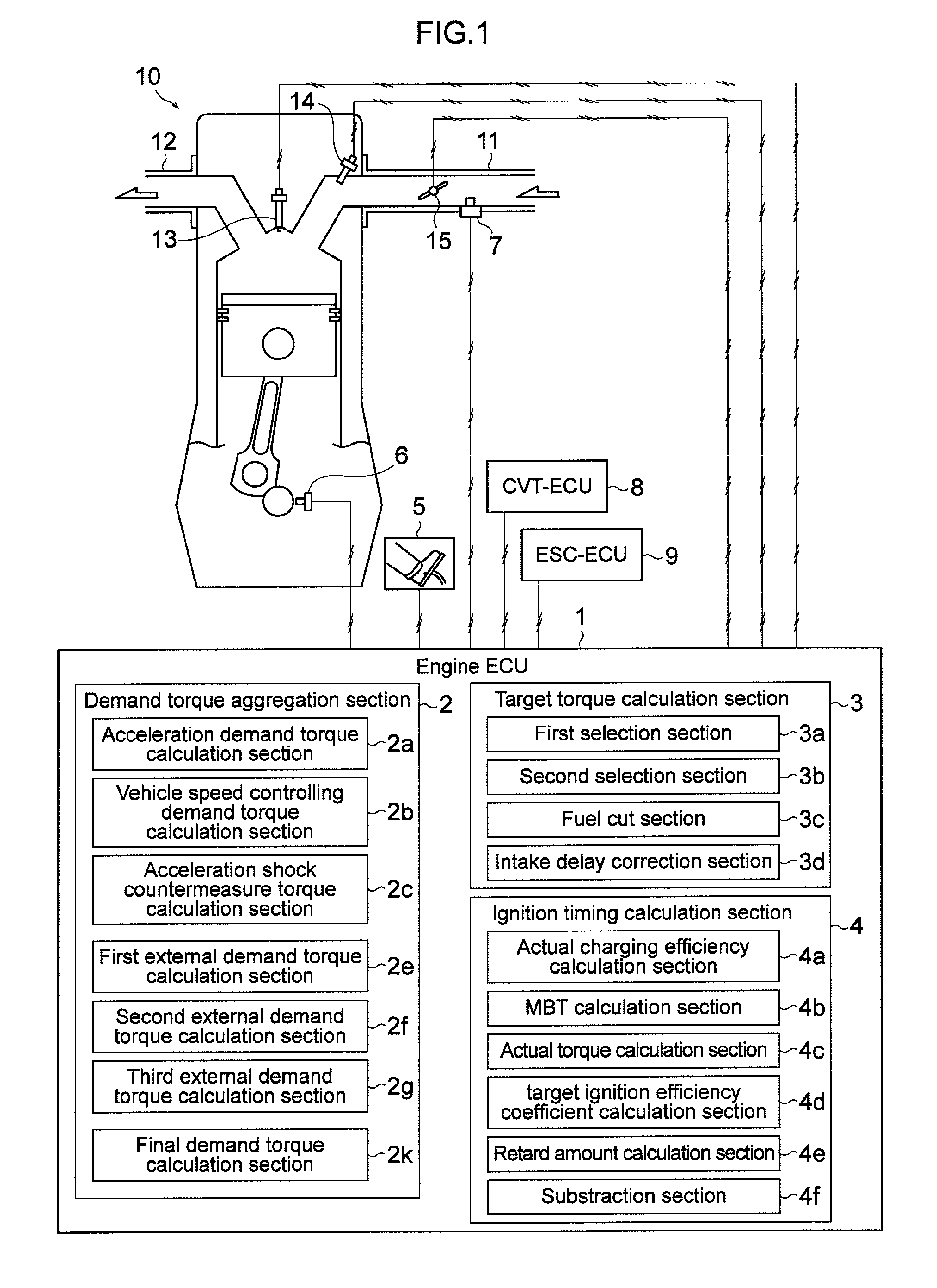
[0024]In the following, an embodiment of an engine controlling apparatus is described with reference to the drawings. It is to be noted that the embodiment described below is illustrative to the end, and there is no intention to eliminate various modifications and applications of the technique not specified in the embodiment described below.

[0025]1. Apparatus Configuration

[0026]A controlling apparatus of the present embodiment is applied to a vehicle-carried engine 10 shown in FIG. 1. Here, one cylinder from among a plurality of cylinders provided in the multi-cylinder four-cycle type engine 10 is shown. An ignition plug 13 is provided at the top of the cylinder in a state in which an end of the plug 13 is projected to the combustion chamber side. Further, an intake path 11 and an exhaust path 12 are connected to the top face of the cylinder head side of the combustion chamber.

[0027]An injector 14, an ETV (Electric Throttle Valve) 15 and an air flow sensor (intake air amount detecti...


PUM


Abstract

An engine controlling apparatus includes an engine speed detection unit that detects an engine speed, and an acceleration operation amount detection unit that detects an acceleration operation amount inputted to an acceleration pedal.The apparatus includes a first calculation unit that calculates an acceleration demand torque based on the engine speed and the acceleration operation amount, a second calculation unit that calculates an external demand torque demanded from an external controlling system, and a third calculation unit that calculates a first target torque and a second target torque based on the acceleration demand torque and the external demand torque.The apparatus includes a fourth calculation unit that calculates a maximum torque which can be generated by the engine at an actual charging efficiency, and a control unit that controls an ignition timing of the engine based on the actual torque and the first target torque.

Description

CROSS-REFERENCE TO THE RELATED APPLICATION[0001]This application incorporates by references the subject matter of Application No. 2010-224013 filed in Japan on Oct. 1, 2010 on which a priority claim is based under 35 U.S.C. §119(a).BACKGROUND OF THE INVENTION[0002]1. Field of the Invention[0003]The present invention is related to a controlling apparatus for controlling an engine mounted on a vehicle.[0004]2. Description of the Related Art[0005]As one of controlling methods for an engine mounted on a vehicle, torque-based (torque demand) control for controlling the intake air amount, fuel injection amount, ignition timing and so forth with reference to the magnitude of a torque demanded to an engine is available. In the torque-based control, the engine is controlled such that, for example, a target value for an engine torque is calculated based on the acceleration opening, engine speed and so forth and a torque having the target value is acquired. Further, in a vehicle in which an ex...

Claims


Application Information

Patent Timeline
IPC IPC(8): G06F19/00
CPCF02D11/105F02D41/1497F02P5/1508F02D2200/1006F02D2200/101Y02T10/42F02D2250/18Y02T10/46F02D2200/602Y02T10/40
Inventor MIYATA, TOSHIYUKIUEDA, KATSUNORITODA, HITOSHISHIBATA, KOJI
Owner MITSUBISHI MOTORS CORP
Learn More