Lightweight sandwich panel heat pipe

a sandwich panel and heat pipe technology, applied in the field of heat pipes, can solve the problems of difficult or even impossible to fabricate high aspect ratio thin diameter pores with the desired porosity, difficult to design a heat pipe, and requires very little maintenance, and achieves high structural performance, easy manufacturing, and high aspect ratio thin diameter pores.

Active Publication Date: 2013-11-12
HRL LAB
View PDF18 Cites 43 Cited by
  • Summary
  • Abstract
  • Description
  • Claims
  • Application Information

AI Technical Summary

Benefits of technology

[0006]Aspects of embodiments of the present invention are directed towards a specifically structural heat pipe that can be easily manufactured to have high aspect ratio thin diameter pores with porosity of the desired dimensions, designed for both high structural performance as well as high thermal performance, and / or be tailored for a variety of applications.

Problems solved by technology

Because heat pipes contain no mechanical moving parts, it typically requires very little maintenance.
As such, it is difficult or even impossible to fabricate high aspect ratio thin diameter pores with porosity of the desired dimensions.
It addition, it is difficult to design a heat pipe that can have both high structural performance as well as high thermal performance.

Method used


Image

  • Lightweight sandwich panel heat pipe
  • Lightweight sandwich panel heat pipe
  • Lightweight sandwich panel heat pipe

Examples


Embodiment Construction

[0054]In the following detailed description, only certain exemplary embodiments of the present invention are shown and described, by way of illustration. As those skilled in the art would recognize, the described exemplary embodiments may be modified in various ways, all without departing from the spirit or scope of the present invention. Accordingly, the drawings and description are to be regarded as illustrative in nature, and not restrictive.

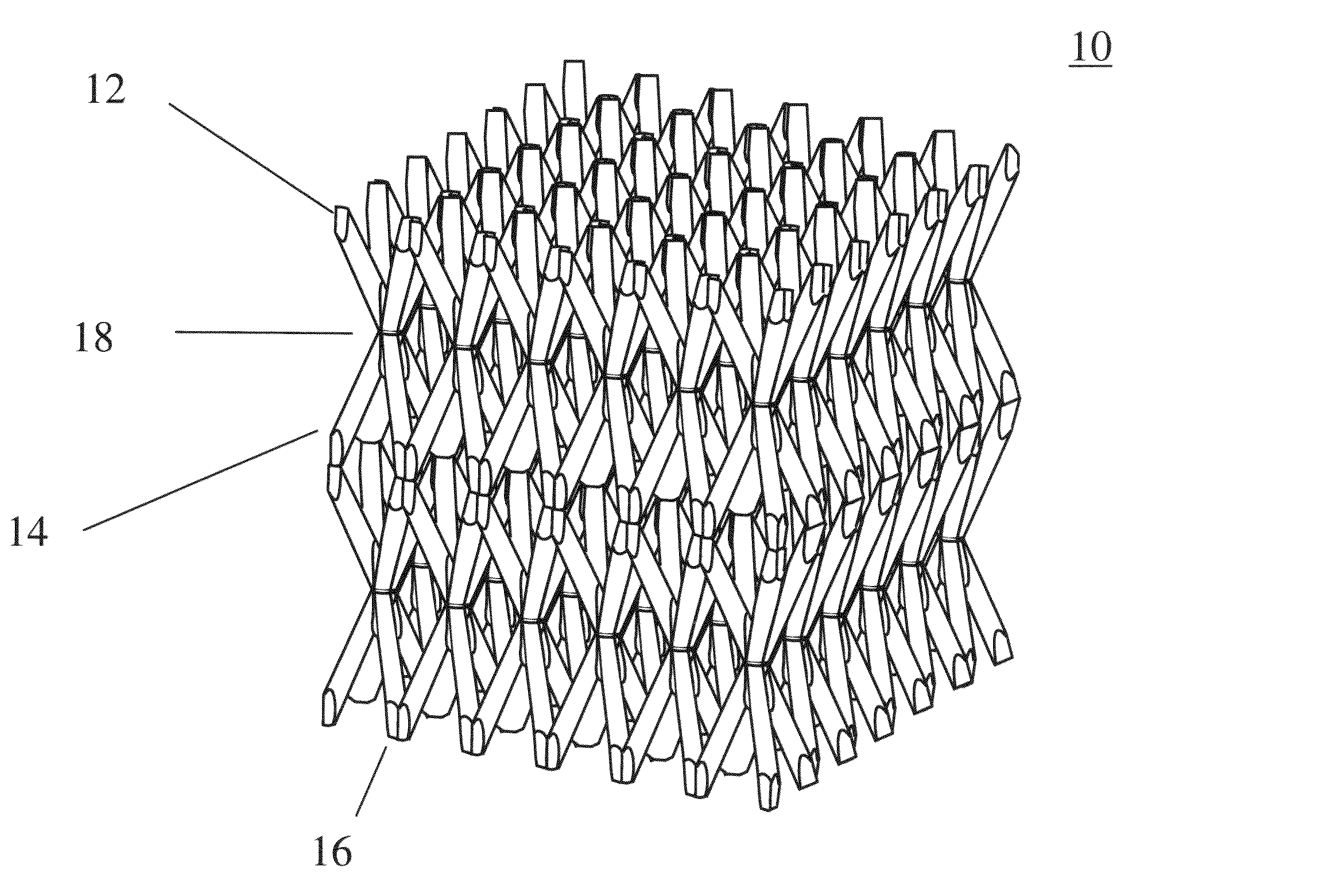
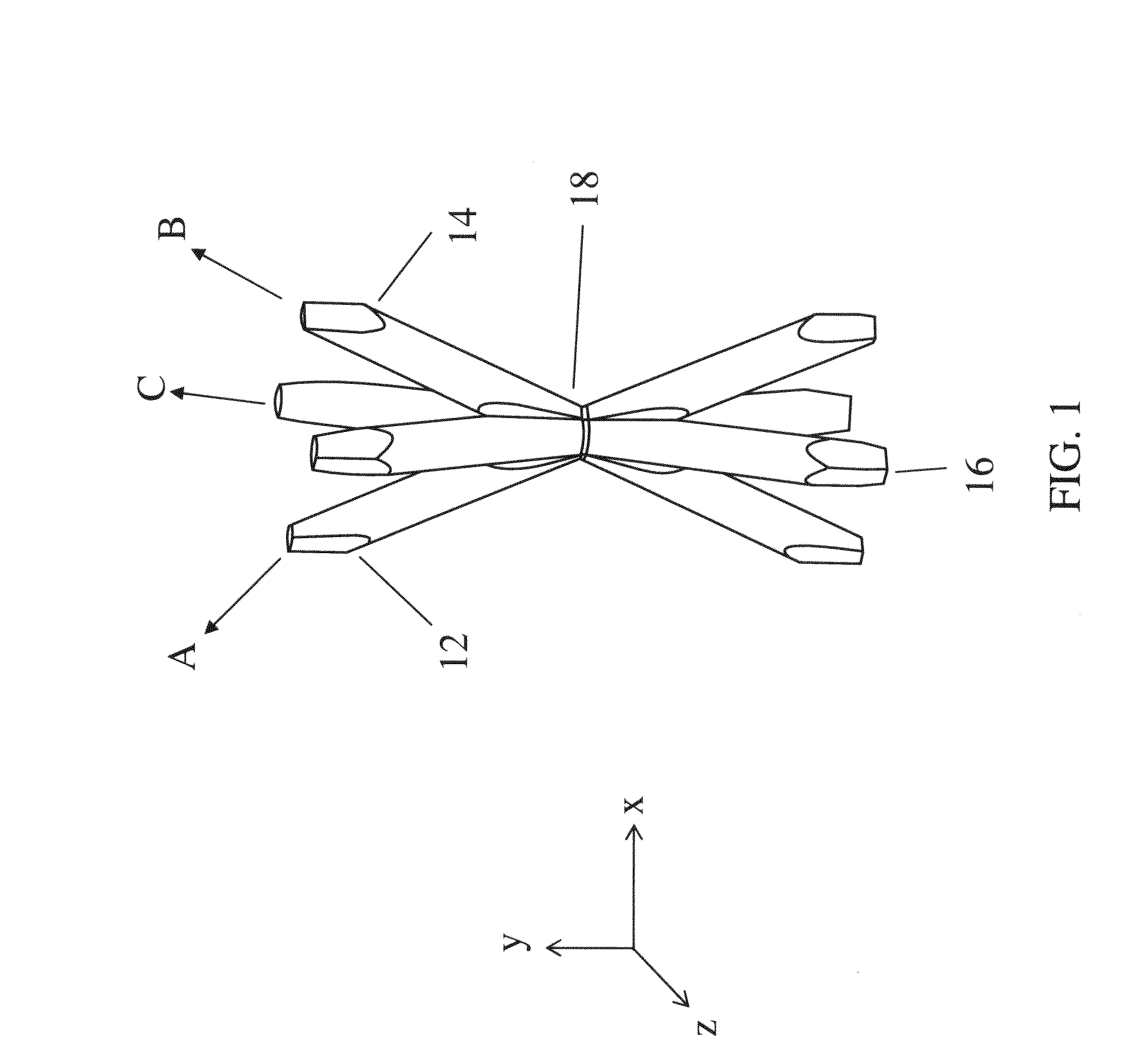
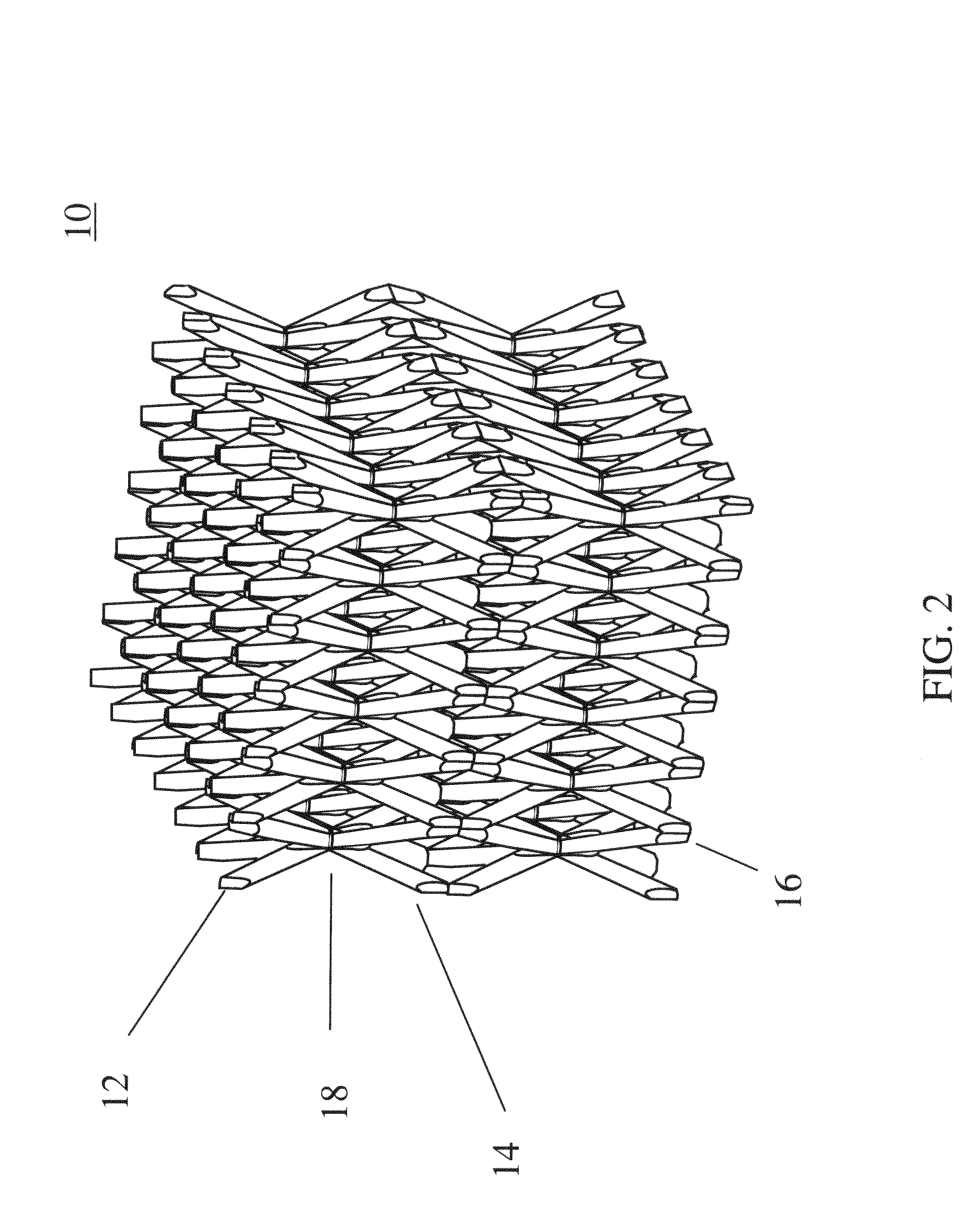
[0055]In the context of embodiments of the present invention, a three-dimensional ordered microstructure is referred to as an ordered three-dimensional structure at the micrometer scale. In one embodiment of the present invention, a heat pipe with a wick structure composed of a three-dimensional ordered microstructure is provided. Here, the heat pipe may be a lightweight sandwich panel heat pipe.

[0056]In one embodiment, the mechanical members of the three-dimensional ordered microstructure have a three-dimensional order that is on a size scal...


PUM

PropertyMeasurementUnit
sizeaaaaaaaaaa
sizeaaaaaaaaaa
sizeaaaaaaaaaa

Abstract

A sandwich panel heat pipe with a three-dimensional ordered open-cellular micro-truss core and a method creating the same. In one embodiment, the sandwich panel heat pipe includes a first face sheet, a second face sheet, the three-dimensional ordered open-cellular micro-truss core between the first face sheet and the second face sheet, and a working fluid in the ordered open-cellular micro-truss core. Here, the three-dimensional ordered open-cellular micro-truss core includes a vapor region and a liquid region, the vapor region is for transporting a vapor phase portion of the working fluid to the liquid region, and the liquid region is for transporting a liquid phase portion of the working fluid to the vapor region.

Description

FIELD OF THE INVENTION[0001]The present invention relates to a heat pipe and a method of creating the same, and more particularly, to a lightweight sandwich panel heat pipe and a method of creating the same.BACKGROUND OF THE INVENTION[0002]A heat pipe is a heat transfer mechanism that can transfer a large amount of heat with a very small difference in temperature between its hot portion (or higher temperature region) and its cold portion (or lower temperature region). Inside a heat pipe, at the hot portion, a working fluid is evaporated into a vapor, and the vapor flows through a vapor region within the heat pipe and condenses on the cold portion into a liquid. The liquid is then moved through a liquid region within the heat pipe (e.g., by gravity and / or capillary action) back to the hot portion to be evaporated again to repeat the heat transfer cycle. Because heat pipes contain no mechanical moving parts, it typically requires very little maintenance. In addition, as a heat transfe...

Claims


Application Information

Patent Timeline
Patent Type & Authority Patents(United States)
IPC IPC(8): F28D15/00F28F13/00H05K7/20
CPCH05K7/20336F28F21/06F28D15/046F28F2260/00Y10T29/49353B23P15/26F28D15/04F28F3/00
Inventor ROPER, CHRISTOPHER S.JACOBSEN, ALAN J.
Owner HRL LAB
Why Eureka
Try Eureka