Scroll fluid machine
a fluid machine and roller technology, applied in the direction of machines/engines, rotary/oscillating piston pump components, liquid fuel engines, etc., can solve the problems of large mechanical loss in bearings, complicated structure, complicated structure, etc., and achieve less mechanical loss, simple structure, and higher thrust load
- Summary
- Abstract
- Description
- Claims
- Application Information
AI Technical Summary
Benefits of technology
Problems solved by technology
Method used
Image
Examples
first embodiment
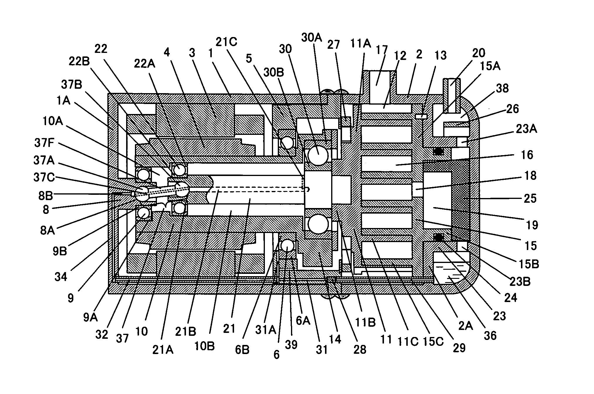
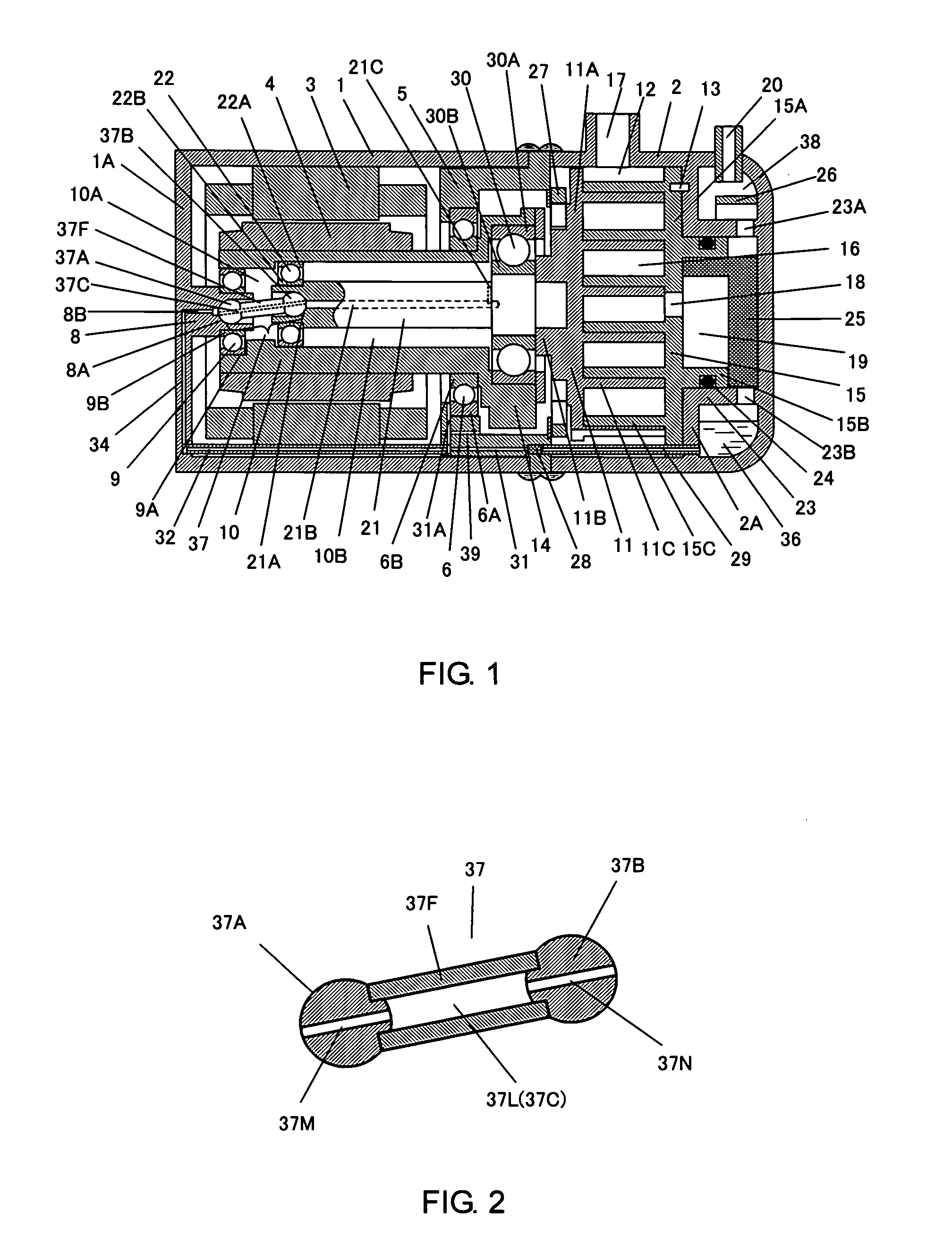
[0031]FIG. 1 illustrates a compressor according to a first embodiment. A motor is formed of a stator 3 and a rotor 4. The stator 3 and a frame 5 are fixed to a casing 1. An outer race 6A of a main bearing 6 is attached to the frame 5. A fixed portion 8 is provided opposite a scroll side of the casing 1, that is, on a bottom 1A. An inner race 9B of a secondary bearing 9 is attached to the fixed portion 8. The fixed portion 8 extends to reach a hollow portion 10A of a rotary shaft 10. The rotary shaft 10 includes hollow portions 10A and 10B each having a different center axis. The center axis of the hollow portion 10A coincides with that of the rotary shaft 10. The center axis of the hollow portion 10B is eccentrically located from the center axis of the rotary shaft 10 by a distance substantially corresponding to the pivoting radius. The hollow portion 10A is positioned at the lower end portion of the rotary shaft 10. The hollow portion 10B is positioned from a leading end to an inte...
second embodiment
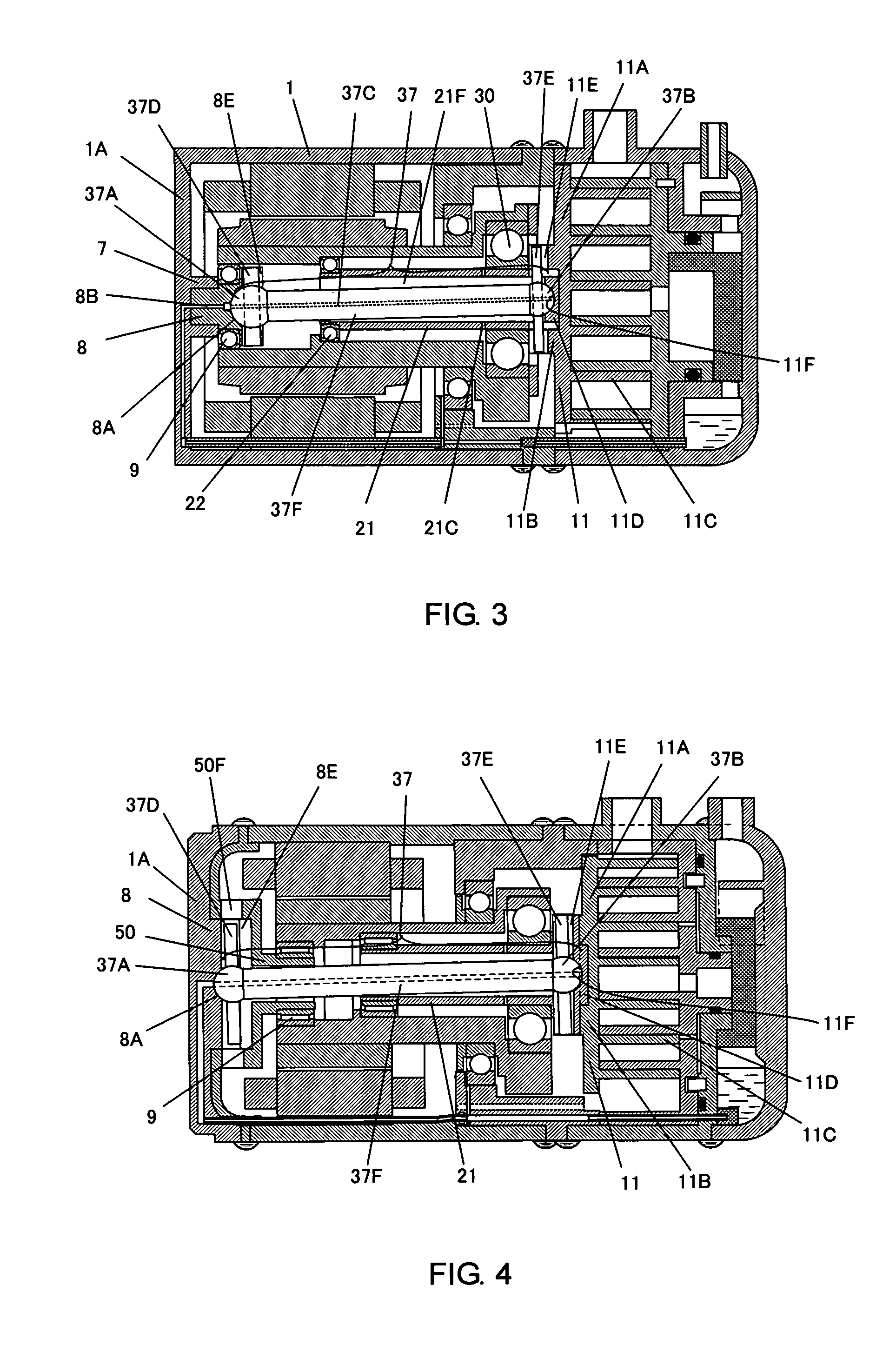
[0046]FIG. 3 illustrates a compressor according to a second embodiment. The same components as those shown in FIG. 1 will be designated with the same codes described in the first embodiment, and explanations thereof, thus will be omitted. The pivot shaft 21 has a hollow portion 21F which penetrates therethrough. The swing column 37 has the sphere 37A at one end, and the sphere 37B at the other end. The swing column 37 penetrates through the hollow portion 21F. The orbiting scroll 11 is mainly formed of the paneling 11A, the boss 11B, the wrap 11C and a spherical base 11D. The spherical base 11D is provided within the boss 11B. The spherical base 11D includes a bearing (concave spherical bearing) 11F at the center portion. The sphere 37B (at the other end of the swing column 37) is swingably fitted to the bearing 11F, and includes a columnar pin 37E. The pin 37E has its axis passing through the core of the sphere 37B. The pin 37E orthogonally crosses the swing column 37. The boss 11B...
third embodiment
[0051]FIG. 4 illustrates a compressor according to a third embodiment. Explanations of the same components and codes shown in FIGS. 1 to 3, which have been described in the first and the second embodiments will be omitted. The orbiting scroll 11 is mainly formed of the paneling 11A, the boss 11B, the wrap 11C and the spherical base 11D. The spherical base 11D is provided inside the boss 11B, and includes the guide groove 11E and the bearing (concave spherical bearing) 11F. The swing column 37 is formed by bonding the cylinder 37F between the spheres 37A at one end and the sphere 37B at the other end. The sphere 37B (at the other end of the swing column 37) includes the columnar pin 37E which protrudes outward. The axis of the pin 37E passes through the core of the sphere 37B. The pin 37E orthogonally crosses the swing column 37. The bearing 11F has the spherical radius which is substantially equal to that of the sphere 37B. The width of the guide groove 11E is substantially equal to...
PUM
 Abstract
Description
Claims
Application Information
 - R&D
- Intellectual Property
- Life Sciences
- Materials
- Tech Scout
- Unparalleled Data Quality
- Higher Quality Content
- 60% Fewer Hallucinations
Browse by: Latest US Patents, China's latest patents, Technical Efficacy Thesaurus, Application Domain, Technology Topic, Popular Technical Reports.
© 2025 PatSnap. All rights reserved.Legal|Privacy policy|Modern Slavery Act Transparency Statement|Sitemap|About US| Contact US: help@patsnap.com


