Electrostatic ion trap

a technology of electrostatic ion traps and ion traps, which is applied in the field of analytical instruments, can solve the problems of substantial baseline offset of noisy spectra and loss of spectral resolution in higher levels, and achieve the effect of improving mass spectra quality and reducing baseline in mass spectra

Active Publication Date: 2013-11-19
MKS INSTR INC
View PDF23 Cites 16 Cited by
  • Summary
  • Abstract
  • Description
  • Claims
  • Application Information

AI Technical Summary

Benefits of technology

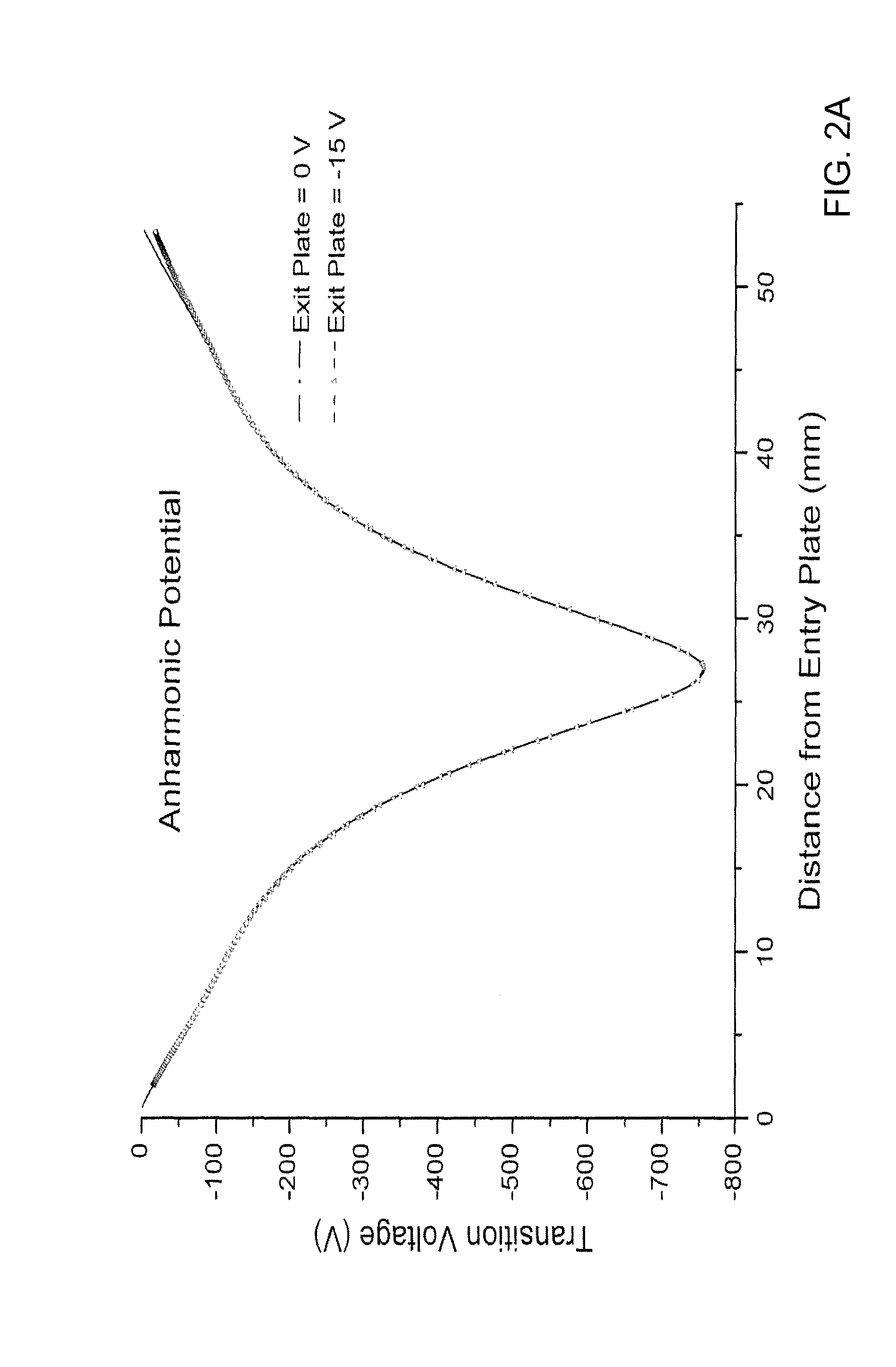
[0017]In another embodiment, an ion trap comprises an electrode structure, including first and second opposed mirror electrodes and a central lens therebetween, that produces an electrostatic potential in which ions are confined to trajectories at natural oscillation frequencies, the confining potential being anharmonic, and a scan control that mass selectively reduces a frequency difference between an AC excitation frequency connected to the electrode structure and a multiple of the natural oscillation frequency of the ions from an excitation frequency lower than the multiple of the natural oscillation frequency of the ions. In one embodiment, the scan control reduces the frequency difference by sweeping the AC excitation frequency at a sweep rate. In some embodiments, the sweep rate can be a nonlinear sweep rate. In certain embodiments, the nonlinear sweep can be composed of concatenated linear sweeps. In another embodiment, the scan control reduces the frequency difference by sweeping the magnitude V of the electrostatic potential at a sweep rate in a direction such that the multiple of the natural oscillation frequency of the ions changes from a frequency higher than the frequency of the AC excitation source.
[0032]In another embodiment, a method of trapping ions in an ion trap includes producing an anharmonic electrostatic potential in which ions are confined to trajectories at natural oscillation frequencies, in an electrode structure that includes first and second opposed mirror electrodes and a central lens therebetween. The method further includes scanning an excitation frequency of an AC excitation source connected to the electrode structure and mass selectively reducing a frequency difference between the AC excitation frequency and a multiple of the natural oscillation frequency of the ions from an excitation frequency lower than the multiple of the natural oscillation frequency of the ions. In one embodiment, the scan control reduces the frequency difference by sweeping the AC excitation frequency at a sweep rate. In another embodiment, the scan control reduces the frequency difference by sweeping a magnitude V of the electrostatic potential at a sweep rate in a direction such that the multiple of the natural oscillation frequency of the ions changes from a frequency higher than the frequency of the AC excitation source. In some embodiments, the sweep rate can be a nonlinear sweep rate.
[0038]This invention has many advantages, such as improved quality of mass spectra at higher pressure (10−4-10−5 Torr) and reduced baseline in mass spectra throughout the operational pressure range of the ion trap (10−4 Torr to 10−10 Torr).

Problems solved by technology

This design produced good quality spectra of high vacuum environments (pressures lower than 10−6 Torr), but produced noisy spectra with substantial baseline offsets and loss of spectral resolution in higher pressure (10−4-10−5 Torr) environments.

Method used


Image

  • Electrostatic ion trap
  • Electrostatic ion trap
  • Electrostatic ion trap

Examples


Embodiment Construction

[0088]A description of example embodiments of the invention follows.

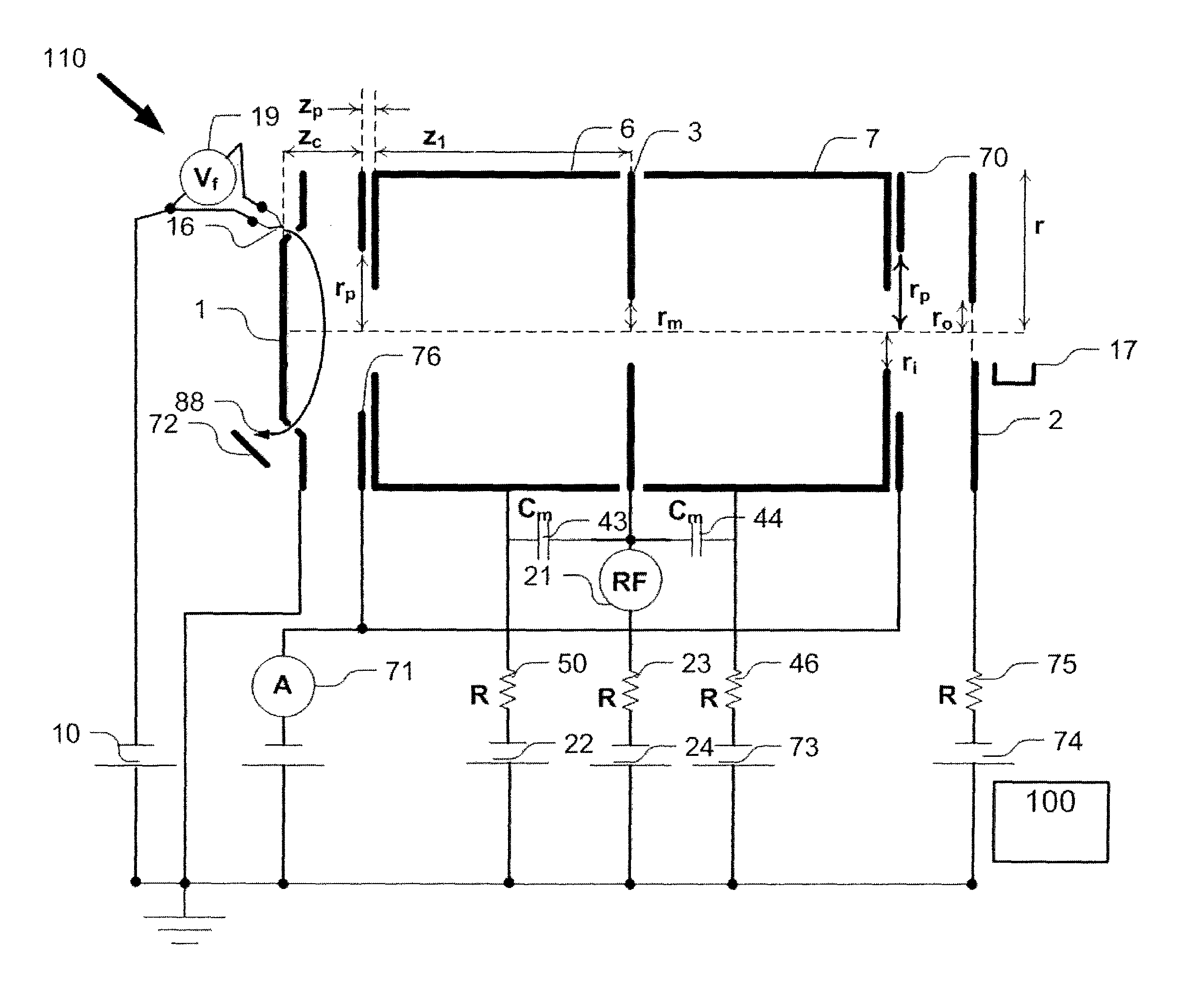
[0089]An ion trap comprises an electrode structure, including a first and a second opposed mirror electrodes and a central lens therebetween, that produces an electrostatic potential in which ions are confined to trajectories at natural oscillation frequencies, the confining potential being anharmonic. The ion trap also includes an AC excitation source having an excitation frequency f that excites confined ions at a frequency of about a multiple of the natural oscillation frequency of the ions, the AC excitation frequency source preferably being connected to the central lens.

[0090]Turning now to FIG. 1, an ion trap 110 comprises an electrode structure made up of two plates 1 and 2, two cup-shaped electrodes 6 and 7, and a flat central lens 3. In this example, each plate 1 and 2 is about 0.025″ thick and about 1″ in diameter. Plate 1 includes a protrusion of about 0.075″ in height and about 0.625″ in largest dimensio...


PUM


Abstract

An ion trap includes an electrode structure, including a first and a second opposed mirror electrodes and a central lens therebetween, that produces an electrostatic potential in which ions are confined to trajectories at natural oscillation frequencies, the confining potential being anharmonic. The ion trap also includes an AC excitation source having an excitation frequency f that excites confined ions at a frequency of about twice the natural oscillation frequency of the ions, the AC excitation frequency source preferably being connected to the central lens. In one embodiment, the ion trap includes a scan control that mass selectively reduces a frequency difference between the AC excitation frequency and about twice the natural oscillation frequency of the ions.

Description

RELATED APPLICATIONS[0001]This application is a continuation of International Application No. PCT / US2010 / 033750, which designated the United States and was filed on May 5, 2010, published in English, which claims the benefit of U.S. Provisional Application No. 61 / 215,501, filed on May 6, 2009, U.S. Provisional Application No. 61 / 176,390, filed on May 7, 2009, U.S. Provisional Application No. 61 / 325,119, filed on Apr. 16, 2010, and U.S. Provisional Application No. 61 / 329,163, filed on Apr. 29, 2010.[0002]The entire teachings of the above applications are incorporated herein by reference.BACKGROUND OF THE INVENTION[0003]A mass spectrometer is an analytical instrument that separates and detects ions according to their mass-to-charge ratio. Mass spectrometers can be differentiated based on whether trapping or storage of ions is required to enable mass separation and analysis. Non-trapping mass spectrometers do not trap or store ions, and ion densities do not accumulate or build up insid...

Claims


Application Information

Patent Timeline
Patent Type & Authority Patents(United States)
IPC IPC(8): H01J49/00
CPCH01J49/4245H01J49/0063H01J49/429G01N27/623
Inventor BRUCKER, GERARDO A.VAN ANTWERP, KENNETH D.RATHBONE, G. JEFFERYHEINBUCH, SCOTT C.SCHOTT, MICHAEL N.HINCH, BARBARA JANEERMAKOV, ALEXEI V.
Owner MKS INSTR INC
Why Eureka
Try Eureka