Pocketed air and fuel mixing tube

a fuel mixing tube and gas turbine engine technology, applied in the direction of machines/engines, mechanical equipment, lighting and heating apparatus, etc., can solve the problems of inefficient combustion, potential unwanted pressure oscillation, damage to that part or the engine itself, etc., and achieve the effect of improving the design of the fuel nozzl

Inactive Publication Date: 2013-11-26
GENERAL ELECTRIC CO
View PDF20 Cites 32 Cited by
  • Summary
  • Abstract
  • Description
  • Claims
  • Application Information

AI Technical Summary

Benefits of technology

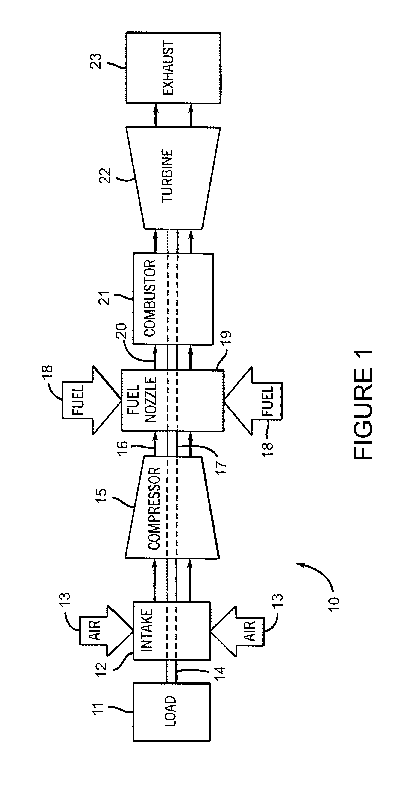
[0006]The present invention provides for an improved fuel nozzle design for use in a gas turbine engine that allows for a more uniform and thorough mixing of fuel and air being fed to the combustor. In one exemplary embodiment, the fuel nozzle includes a plurality of uniquely configured fuel / air mixing tubes, each of which comprises a pair of concentric hollow cylinders that define a ring-like annular path for the flow of fuel between the two hollow cylinders in each mixing tube, a plurality of air injection slots formed in the concentric hollow cylinders that create corresponding air flow paths from the outside into the interior of each mixing tube, and one or more fuel injection ports formed in selected ones of the air injection slots that allow for the flow of fuel from the annular path formed by the hollow cylinders directly into the air flow path. The new mixing tube and nozzle designs result in significantly improved mixing and improved thermodynamic behavior of the fuel and air mixture downstream of the nozzle before it reaches the combustor. The present invention also contemplates a new fuel and air combustion system for a gas turbine engine comprising a combustor, a fuel supply for providing hydrocarbon fuel to the combustor, a compressed air supply to the combustor and an improved fuel and air nozzle design upstream of the combustor using the unique mixing tube configuration described below.

Problems solved by technology

It is known that air and fuel pressures within each combustor can vary over time, often resulting in unwanted variations of the air / fuel mixture that cause incomplete (and thus less efficient) combustion, as well as potential unwanted pressure oscillations in the combustion gases at certain frequencies.
If a combustion frequency corresponds to the natural frequency of a component part or subsystem within the turbine engine, damage to that part or the engine itself may occur over time even during normal operation.
Operating at low combustion temperatures to lower the NOx emissions can result in incomplete or partially incomplete combustion, which in turn can lead to the production of excessive amounts of unburned hydrocarbons (HC) and carbon monoxide (CO), as well as lower power output and lower thermal efficiency of the engine.
Higher combustion temperatures, on the other hand, tend to improve thermal efficiency and lower the amount of HC and CO, but can still result in a higher output of NOx if the combustion mixture and operating conditions are not properly monitored and controlled.
That is, burning (oxidation) occurring uniformly in the entire fuel / air mixture tends to reduce the potential for high levels of HC and CO that result from incomplete combustion.

Method used


Image

  • Pocketed air and fuel mixing tube
  • Pocketed air and fuel mixing tube
  • Pocketed air and fuel mixing tube

Examples


first embodiment

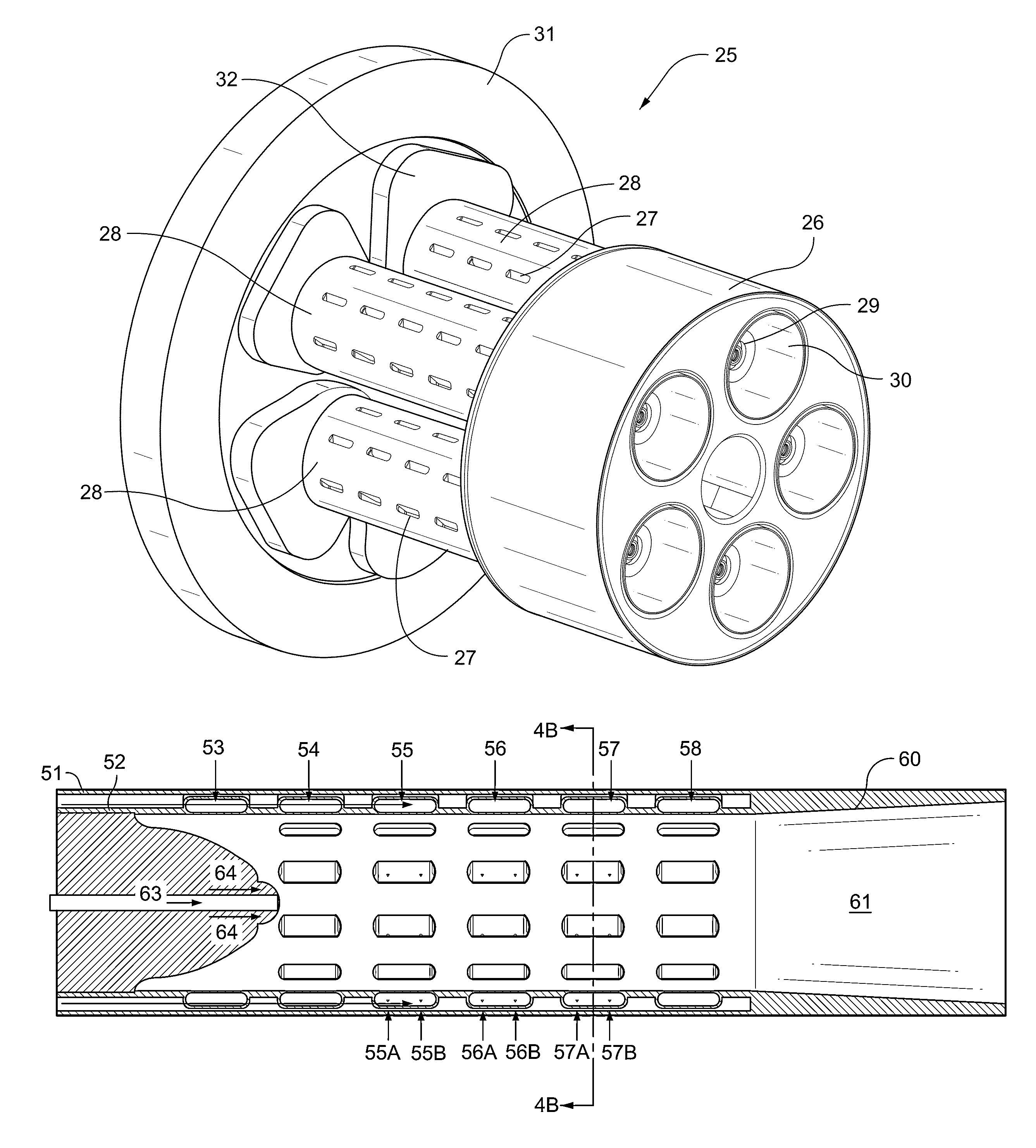
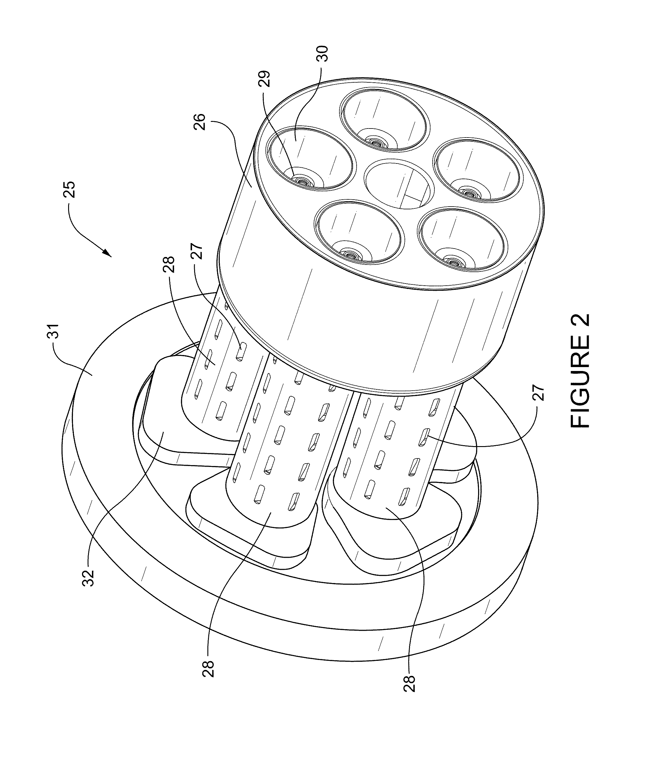
[0034]FIG. 2 of the drawings is a perspective view of a fuel nozzle assembly depicting in greater detail a plurality of fuel and air mixing tubes according to the invention, with each air and fuel mixing tube having a uniformly-spaced slotted configuration as shown. The fuel nozzle assembly, depicted generally as 25, includes a plurality of mixing tubes (in this example five tubes, each identified as item 28), with all tubes secured to a fuel nozzle assembly end plate 31 by virtue of corresponding individual mounting flanges as shown at 32. In this embodiment, the mixing tubes are secured to the end plate and oriented at equidistant angular positions relative to the center of end plate 31 and thus secured parallel to one another along a common longitudinal axis.

[0035]As FIG. 2 illustrates, each of the mixing tubes 28 in the fuel nozzle assembly 25 includes a plurality of uniformly-spaced fuel and air injection slots shown by way of example as 27 and described in greater detail below...

embodiment 170

[0064]FIG. 10 is cross-sectional view of a further embodiment 170 of the present invention illustrating the use of a gas and liquid fuel injector in combination with the plurality of fuel / air slots and concentric tubes in the mixing tube embodiment described in earlier figures. This embodiment includes concentric tubes 171 and 172 and a plurality of uniformly spaced rows of angled slots 173 and 182 as described. The first row of angled slots in the mixing tube provide a prescribed amount of supplemental air above ambient temperature down through passage 178 which serves to atomize a fixed amount of liquid fuel entering the nozzle through liquid fuel passage 174 in the center of the nozzle. The liquid fuel passes under pressure through a plurality of tiny, pinhole-type openings in the injection head (see injection ports 176A and 176B). Once again, a portion of the liquid fuel impacts against the interior wall of atomizing bellows 180, while the remainder passes out of the injector in...


PUM


Abstract

An improved mixing tube design and fuel nozzle that allows for a more uniform and thorough mixing of fuel and air being fed to the combustor of a gas turbine engine, wherein each of a plurality of mixing tubes comprises a pair of concentric hollow cylinders that define a ring-like, annular path for the flow of fuel between the two hollow cylinders in each mixing tube, a plurality of air injection slots formed in the concentric hollow cylinders defining corresponding air flow paths from the outside into the interior of each mixing tube, and one or more fuel injection ports formed in selected ones of the plurality of air injection slots that allow for the flow of fuel from the annular path formed by the hollow cylinders into the air flow path, resulting in significantly better mixing and improved thermodynamic behavior of the fuel and air mixture downstream of the nozzle and upstream of the combustor.

Description

BACKGROUND OF THE INVENTION[0001]The present invention relates to combustion systems for gas turbine engines and, more particularly, to an improved fuel nozzle design that significantly enhances the mixing of fuel and air prior to combustion, thereby increasing the overall efficiency of an entire gas turbine system, while reducing unwanted pressure fluctuations in the combustion gases and limiting the release of undesirable gas emissions into the atmosphere.[0002]Gas turbine engines typically include one or more combustors that burn a mixture of compressed air and fuel to produce hot combustion gases that drive the turbine to produce electricity and normally include multiple combustors positioned circumferentially around a rotational axis. It is known that air and fuel pressures within each combustor can vary over time, often resulting in unwanted variations of the air / fuel mixture that cause incomplete (and thus less efficient) combustion, as well as potential unwanted pressure osc...

Claims


Application Information

Patent Timeline
Patent Type & Authority Patents(United States)
IPC IPC(8): F02G3/00F02C1/00
CPCF23R3/286
Inventor PARSANIA, NISHANT GOVINDBHAIBOARDMAN, GREGORY ALLEN
Owner GENERAL ELECTRIC CO
Why Eureka
Try Eureka