Sound proof membrane

a sound-proof membrane and membrane technology, applied in the direction of adhesive processes, floors, building components, etc., can solve the problems of reducing the degree of noise vibration of reducing the intensity of structure-borne noise produced by walls or floor structures when forced into vibration, and reducing the transmission of sound waves. , to achieve the effect of dissipating sound vibrational energy, preventing noise vibrations from being transmitted to the surrounding environment, and reducing the transmission of sound vibration

Active Publication Date: 2013-11-26
POLYGLASS
View PDF9 Cites 35 Cited by
  • Summary
  • Abstract
  • Description
  • Claims
  • Application Information

AI Technical Summary

Benefits of technology

[0025]No existing sound proof membrane meets the sound requirements at the weight and thickness of the underlayment disclosed herein. The disclosed underlayment membrane which is positioned between the concrete slab and hard tile surface consists of a decoupling layer, a barrier layer and dampening layer in such a way as to prevent noise vibrations from being transmitted to the surrounding environment. The decoupling layer reduces the transmission of sound waves while the barrier layer prevents the dampening layer from penetrating the decoupling layer and imparts some rigidity to the system and acts in part like a secondary decoupling layer that contributes to dissipating sound vibrational energy. The dampening layer acts as a dampening material with sound absorbing, sound reducing characteristics that can also have viscoelastic and elastic properties or non-viscoelastic properties depending on the material used and can also act as an adhesive to attach the membrane to the concrete. The dampening material is capable of storing strain energy when deformed, while dissipating a portion of this energy through hysteresis.

Problems solved by technology

The disturbing influences of airborne noise generated within a building generally are limited to areas near the noise source.
These vibrating surfaces, which behave somewhat like the sounding board of a piano, amplify and transmit the vibrational energy to the surrounding air, causing pressure fluctuations resulting in airborne noise to adjacent areas.
The intensity of structure borne noise produced by a wall or floor structure when it has been forced into vibration is generally more intense and harder to dissipate than an airborne sound wave.
Hard-finish flooring materials (e.g., ceramic tiles) adhered directly to concrete slabs does not improve the Impact Insulation Class rating achieved by the concrete itself.
Adding an acoustical ceiling to the home or office can be very expensive and adds additional labor and material costs.
This option is very expensive and requires extra space in renovating a building or in new construction and is not practical in many existing buildings today.
There are several types of underlayments in the market used to reduce sound between a concrete slab and a hard tile surface that appears to meet the Impact Insulation Class rating of 50 minimum but each of these materials has a disadvantage.
Shredded or foamed rubber can be very expensive, hard to install, is very heavy 1.0 to 1.4 lbs / square foot at a 6 mm thickness and it requires 6 mm of thickness to meet the Impact Insulation Class 50 minimum rating required by the International Building Codes.
Cork (both natural and synthetic) and natural fiber mats can reduce the noise and approach the International Building Code requirements of 50 minimum Impact Insulation Class rating if thick enough, but these materials are not recommended for wet or humid areas since mold and mildew can develop over time and can cause health problems.
Unfortunately, current bitumen and modified bitumen membranes in the market for floor underlayments have failed to reach the Impact Insulation Class rating of 50 minimum required by the International Building Code.

Method used


Image

  • Sound proof membrane
  • Sound proof membrane
  • Sound proof membrane

Examples


Embodiment Construction

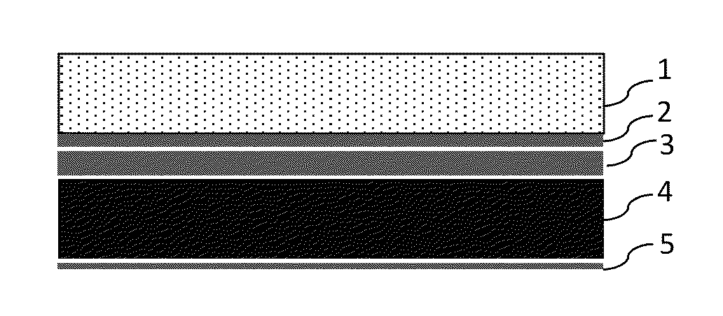
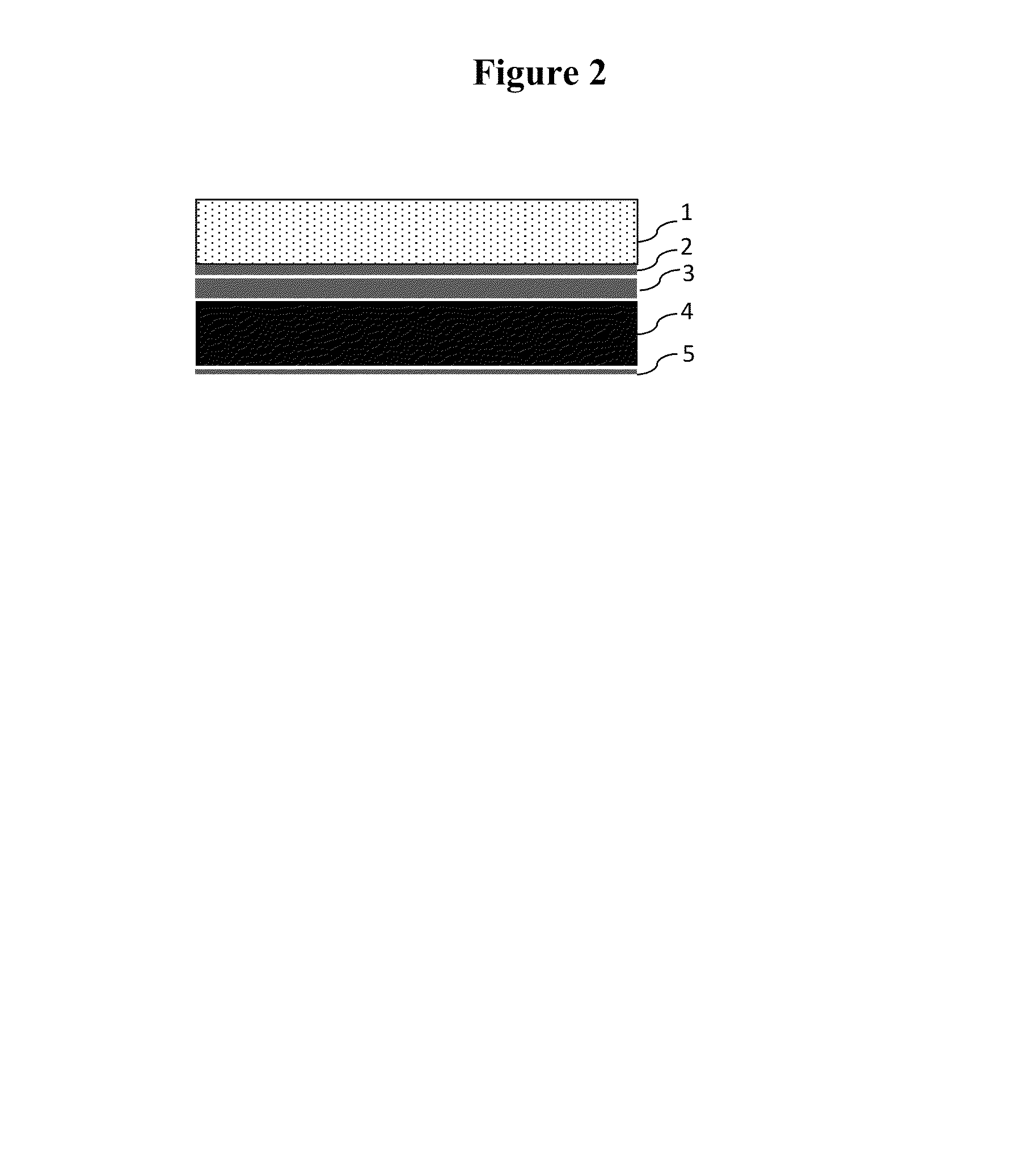
[0031]FIG. 2 is a schematic cross-sectional view of the construction of one embodiment. A generic example of the construction consists of a decoupling layer 1, typically adhered with an adhesive layer 2 to a barrier layer 3 with a dampening layer 4 adhered to the opposite side of the barrier layer. The separation of decoupling layer 1 from the dampening layer 4 enhances the sound reduction properties. A release material 5 can be used to prevent the dampening layer from sticking to itself if the material is wound into a roll or stacked on top of itself.

[0032]A decoupling layer is a material used in the separation of previously linked systems so that they may operate independently. The decoupling layer separates the barrier layer from the surface to be applied on the sound barrier membrane, such as tile, which will applied on the sound barrier membrane. The decoupling layer also helps reduce sound transmission. The decoupling layer 1 can consist of various types or combinations of mat...


PUM


Abstract

A sound barrier membrane comprises of a decoupling layer, a barrier layer and a dampening layer. The membrane also provides crack isolation, and acts as a vapor barrier. Numerous materials are disclosed which can be used to create these layers. Methods for assembly of the sound barrier membrane are also disclosed.

Description

BACKGROUND[0001]The control of noise in the home, office, factory, automobile, train, bus, airplane, etcetera involves reducing the travel or transmission of both airborne noise and structure borne noise, whether generated by sources within or outside your environment.[0002]Airborne noise is produced initially by a source which radiates directly into the air. Many of the noises we encounter daily are of airborne origin; for example, the roar of an overhead jet plane, the blare of an auto horn, voices of children, or music from stereo sets. Airborne sound waves are transmitted simply as pressure fluctuations in the open air, or in buildings along continuous air passages such as corridors, doorways, staircases and duct systems. The disturbing influences of airborne noise generated within a building generally are limited to areas near the noise source. This is due to the fact that airborne noises are less intense and are easier to dissipate than structure borne noise.[0003]Structure bo...

Claims


Application Information

Patent Timeline
Patent Type & Authority Patents(United States)
IPC IPC(8): E04F15/20
CPCE04F15/203E04F15/182
Inventor GRUBE, LOUIS L.ACHA, BETIANA ANDREA
Owner POLYGLASS
Why Eureka
Try Eureka