Power line communication system

a communication system and power line technology, applied in transmission systems, surveillance, reradiation, etc., can solve the problems of short circuit, system not conveying information about load, changing the time or frequency domain characteristics of current drawn from supply, etc., to reduce the effect of reducing the power loss within the modulation circui

Inactive Publication Date: 2013-11-26
THE AUTONOMOUS WELL +1
View PDF47 Cites 4 Cited by
  • Summary
  • Abstract
  • Description
  • Claims
  • Application Information

AI Technical Summary

Benefits of technology

[0045]A preferred feature is that the modulation time period is limited to a known pre-set value to reduce the power loss within the modulation circuit.
[0047]Preferably, the modulation time period is triggered to occur only at times of reduced current flow to the inductive load thereby reducing the power loss within the modulation circuit.
[0048]Preferably, the modulation time period is triggered to occur only at times of reduced voltage applied to the inductive electric load thereby reducing the power loss within the modulation circuit.

Problems solved by technology

Such systems do not convey information about the load but use the communications capabilities of the existing power system.
It is known that faults within a motor or other electrical load may change the time or frequency domain characteristics of a current drawn from a supply.
This is due to the characteristics of the motor being altered due to the presence of faults.
A source of such faults is short circuits between windings in an inductive (magnetically coupled) load.
Such short circuits cause amplitude changes in the current and changes in the phase current cause imbalance in poly-phase machines.
It is also known that mechanical faults in a rotor or bearing faults within a motor will cause changes in the frequency content of the current drawn by the motor.
Such systems are susceptible to phase-to-earth faults.
This can create a loss of communications and therefore cannot be used with earthed electrical systems.
A disadvantage of this method is that all ground loop communications will fail if any of the IELs or their power feeds become grounded.
A disadvantage of these types of methods is that if applied to a signal between phases rather than phase-to-earth, coupling is required between two motor terminals of potentially high voltage.
This is therefore a disadvantage as a special design is required to allow insulation testing.
Previous communications systems also require special high voltage filter or coupling devices to remove power frequencies which not only adds to the complexity and cost of the device, but also adds to its relative size.

Method used


Image

  • Power line communication system
  • Power line communication system
  • Power line communication system

Examples


Embodiment Construction

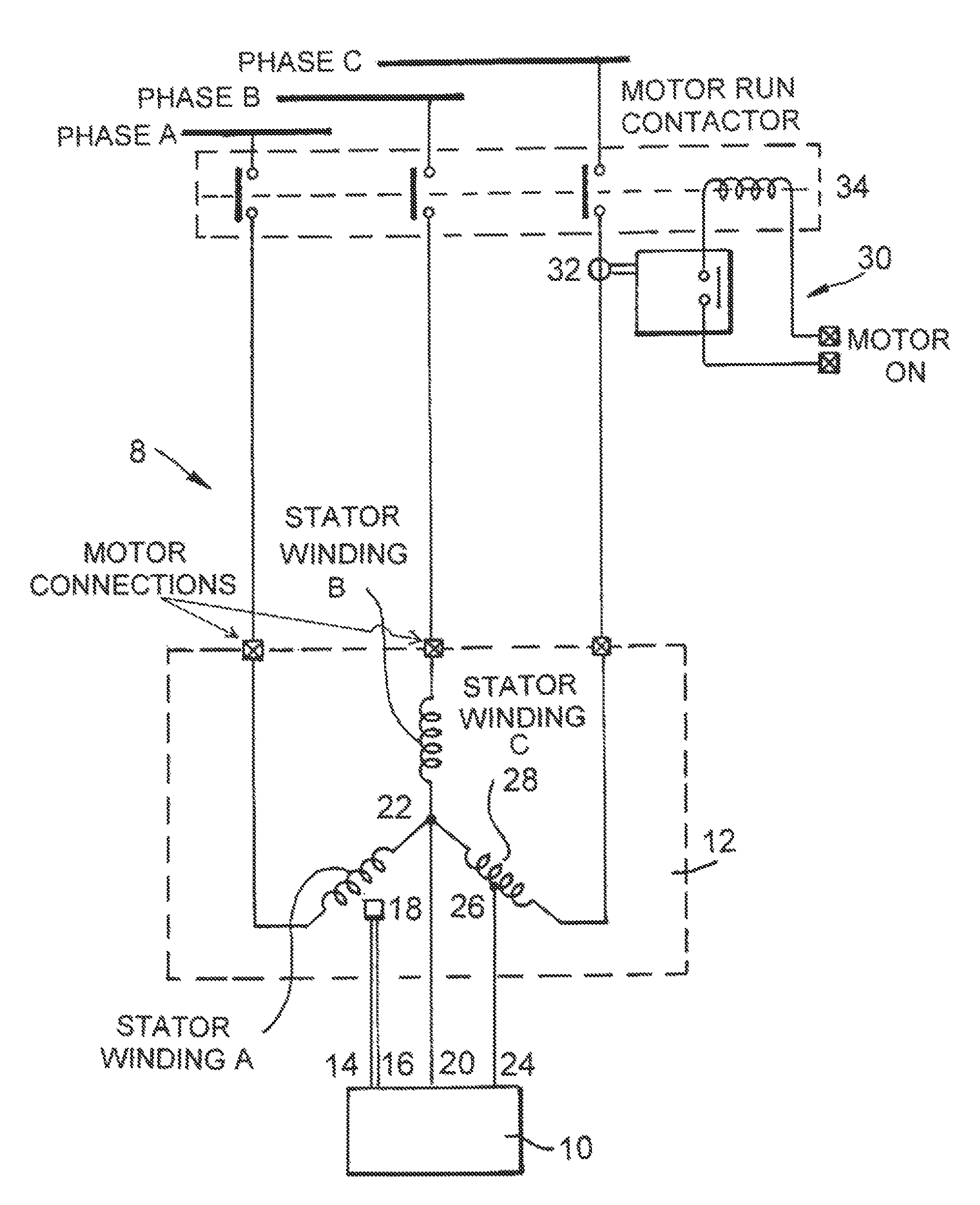
[0063]In FIG. 1 is shown an over-temperature system 8 wherein there is a transmitter 10 connected to a three-phase, star wound induction motor 12 with 300 windings per phase and a phase to phase voltage requirement of 440 V AC rms.

[0064]The transmitter trigger input 14, 16 is connected to a normally open motor thermistor 18, in phase A, and a first modulation input 20, is connected to a neutral point 22 of the motor 12.

[0065]A second modulation input 24 is connected to a turn 26 of stator winding 28. To achieve a certain signal to noise ratio, turn 26 is the 270th turn in the stator winding 28, causing a voltage across the neutral point 22 and turn 26 of approximately 25.4 V AC rms.

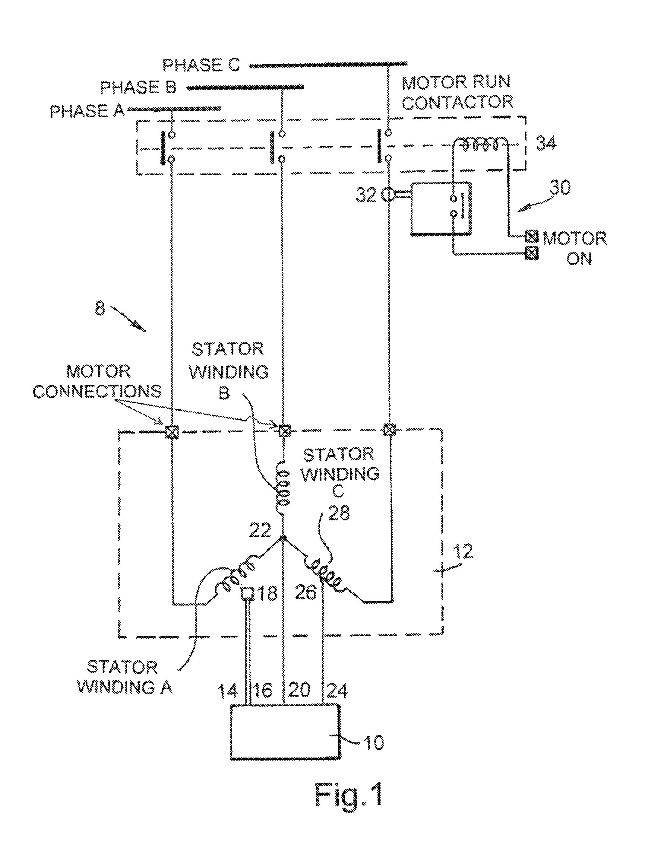
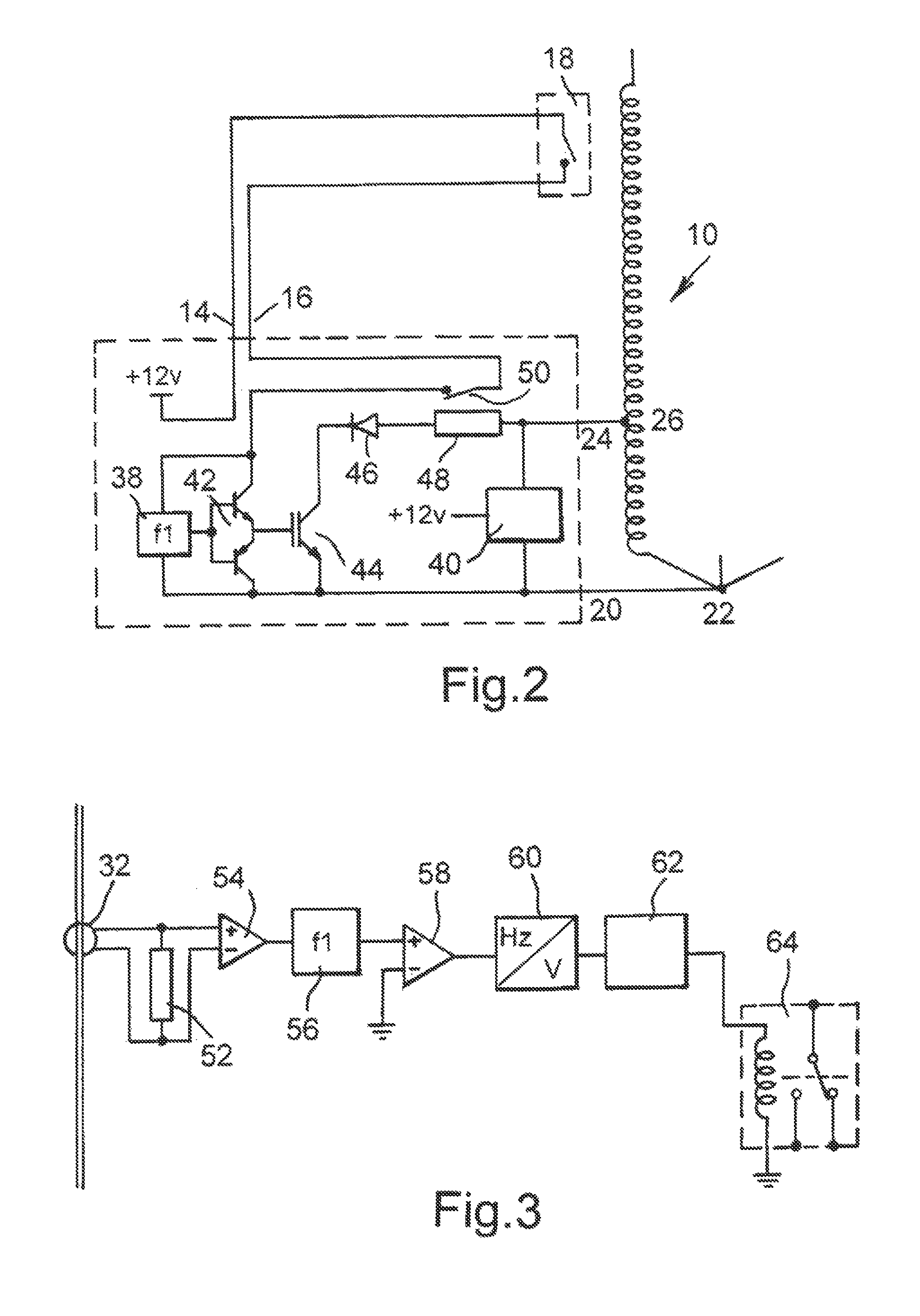
[0066]A receiver 30 is located close to the power source. The receiver 30 has a current transformer 32 which is clamped around the same phase to that of the transmitter's second modulation input 24. In FIG. 1 the modulation input 24 is in Phase C.

[0067]As shown in FIG. 2, the transmitter 10 comprises a mo...


PUM


Abstract

This invention relates to a power line communication (PLC) system wherein the power supply line supplies power and also acts as a communications supply line. A receiver is able to detect small changes in the modulated transmitted information and thereby shut down the circuit. The invention is particularly suitable for use where the IEL is remote from the power supply such as, for example, in down hole oil production situations where very long power cables are used.

Description

RELATED APPLICATIONS[0001]This application is a continuation of U.S. patent application Ser. No. 10 / 030,363 filed Jan. 2, 2002, which is the U.S. national phase of PCT Patent Application No. PCT / GB00 / 02529 filed Jun. 30, 2000, which claims priority of United Kingdom Application No. 9915298.5 filed Jul. 1, 1999.FIELD OF THE INVENTION[0002]The present invention relates to a power line communication system and method. More particularly, the present invention relates to a power line communications system wherein the power frequency in an inductive electric load (IEL) is used as a signal carrier. The invention is particularly suitable for use where the IEL is remote from the power supply such as, for example, in down hole oil production situations where very long power cables are used.BACKGROUND OF THE INVENTION[0003]Power line communication systems are generally well known. One known system modulates the current from a main power supply to signal between units located on a common supply...

Claims


Application Information

Patent Timeline
Patent Type & Authority Patents(United States)
IPC IPC(8): H04M11/04E21B47/00E21B47/12H02J13/00H04B3/54
CPCE21B47/0007E21B47/122H02J13/0048H04B3/54H04B2203/5491H04B2203/5425H04B2203/5466H04B2203/5475H04B2203/5416E21B47/008E21B47/13H02J13/0001Y04S10/52H02J13/00009
Inventor ROBERTSON, MARK PATRICKHOSSACK, GRAEME PETER
Owner THE AUTONOMOUS WELL
Why Eureka
Try Eureka