Wastewater collection flow management system and techniques

a wastewater collection and flow management technology, applied in the field of wastewater collection systems, can solve the problems of increasing the energy cost and wear and tear of costly equipment, requiring the use of expensive special-purpose trucks, and affecting the operation efficiency of biological treatment processes utilized in the treatment plant, so as to reduce the maintenance requirement and increase the threshold level of activation

Active Publication Date: 2013-11-26
DATA FLOW SYST
View PDF95 Cites 44 Cited by
  • Summary
  • Abstract
  • Description
  • Claims
  • Application Information

AI Technical Summary

Benefits of technology

[0032]The invention may still further include a method of reducing maintenance requirement on pumps of a pump station having transceivers on it force main feeding a wastewater treatment facility. The method may comprise the steps of causing transceivers of each pump station to notify a central location of the status of the wet well and the identity of any pumps running, and causing the central location to send information to said transceivers, if any relatively small pump is running on a force main, to increase the threshold level of activation for wet wells associated with relatively larger pumps on that force main and if no relatively smaller pumps are operating sending information to activate larger pumps at full pressure output, so that no relatively smaller pumps are operating on a force main at the same time that a larger pump is running on that force main.

Problems solved by technology

Wastewater collection and treatment systems often operate under conditions in which pumps operate inefficiently, causing increased energy cost and wear and tear on costly equipment.
Further, peak flows into the treatment plant result in accidental spillages and impede the operational efficiency of the biological treatment processes utilized in the treatment plant.
Further, there are times when flow is inadequate to keep the force mains free of sediment, requiring the use of expensive special purpose trucks.
In addition, the operational requirements of the various force main sometimes allows small pumps to run at the same time as larger pumps thereby causing the smaller pumps to operate against the higher pressure from the larger pumps resulting in considerable inefficiency in the operation of the smaller pumps.
Also, existing systems frequently encounter situations where the wet wells to do not get pumped down sufficiently and they therefore begin to generate septic conditions with the accompanying unpleasant smells.

Method used


Image

  • Wastewater collection flow management system and techniques
  • Wastewater collection flow management system and techniques
  • Wastewater collection flow management system and techniques

Examples


Embodiment Construction

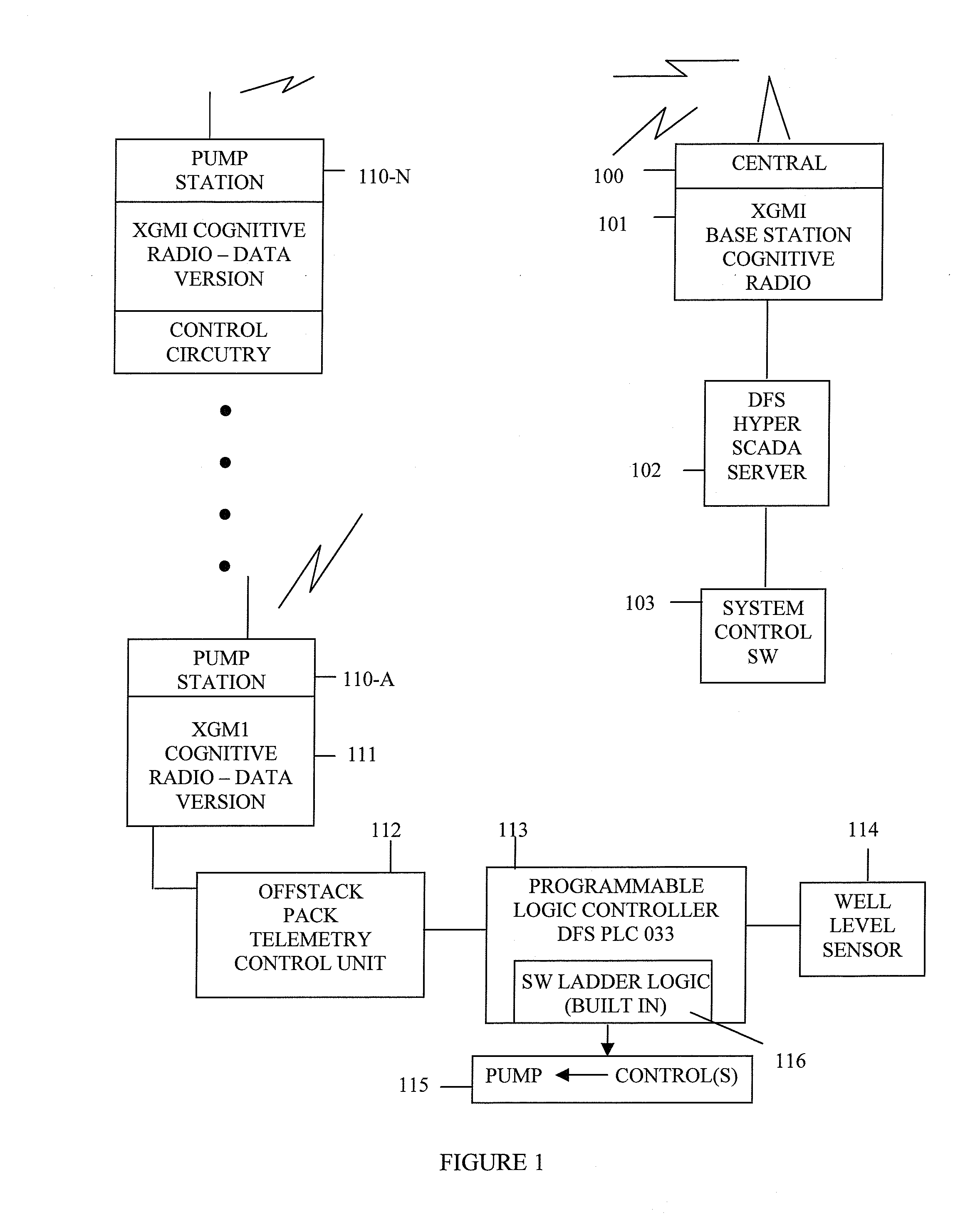
[0051]FIG. 1 is a block diagram illustrating how a plurality of pump stations communicate with a central server in a wastewater treatment system in accordance with one aspect of the invention. A central station 100 includes a base station 101, preferably including an XGMI Cognitive Radio for communicating with remotely located pump stations. Commands are sent to the pump stations over the base station radio and are generated by a server process running, preferably, on a DFS hyper SCADA server 102. The server is controlled by system control software 103 described more hereinafter

[0052]A plurality of stations 110-A through 110-N communicate with the central base station using, preferably, radio links. Almost any type of communication link is possible when designing a system to utilize the benefits of the disclosed invention. These can include microwave, optical (e.g. laser), wireline, optical fiber, microwave communication links and the like. Preferably, however, radio communication l...


PUM


Abstract

Reductions in energy consumption and maintenance requirements for operating a wastewater treatment plant are achieved by controlling the operation of pumps at pump stations along a force main in a systematic fashion. The operation of the pumps is controlled to manage the flow of wastewater along the force main to minimize energy consumption, to eliminate sediment, to manage peak pressures encountered by smaller pumps and to avoid septic conditions.

Description

CROSS REFERENCE TO RELATED APPLICATIONS[0001]This application claims priority to provisional application Ser. No. 60 / 870,862, filed on Dec. 20, 2006, entitled “Wastewater Collection Flow Management System” the contents of which are hereby incorporated into this application by reference in its entirety.BACKGROUND OF THE INVENTION[0002]1. Field of the Invention[0003]The present invention relates in general to wastewater collections systems for wastewater treatment plants, and is particularly directed to pump management, wastewater treatment plant inflow management, sediment elimination, pressure management and septic elimination in wastewater collection systems, wherein an improvement to the operation of wastewater collection systems is made by modulating the operation of the pumping stations systematically, rather than allowing pumps to operate independently.[0004]2. Description of the Prior Art[0005]In a wastewater collection service area, many pump stations often pump wastewater to...

Claims


Application Information

Patent Timeline
Patent Type & Authority Patents(United States)
IPC IPC(8): G05D7/00E03B1/00G08B21/10G05D11/00F23N1/00
CPCG05D9/12Y10T137/2577Y10T137/0324Y10T137/2529Y10T137/2499Y10T137/2511
Inventor SMAIDRIS, THOMAS F.
Owner DATA FLOW SYST
Why Eureka
Try Eureka