
High-lift system for an aircraft with a main wing and an adjustable slat

a technology of adjustable slats and lift systems, which is applied in the direction of airflow influencers, instruments, navigation instruments, etc., can solve the problems of generating acoustic fluctuations, generating sound waves, and affecting the sound quality of lifts

Active Publication Date: 2013-12-03
AIRBUS OPERATIONS GMBH
View PDF26 Cites 5 Cited by
  • Summary
  • Abstract
  • Description
  • Claims
  • Application Information

AI Technical Summary

Benefits of technology

The invention aims to create a simple and safe method to reduce flow noise in a high-lift system that is flexible and can adjust to changing flow conditions. This method should have a minimal impact on the air forces on the wing.

Problems solved by technology

Presently the flow around the lift-generating surfaces is a significant contributor to noise generation of aircraft in the landing approach.
The accelerated movement of the vortices and in particular their exit from the gap result in the emission of sound waves, wherein the sudden impedance jump between the solid wall and the free airflow when flowing over the trailing edge of the slat results in generating acoustic fluctuations as a result of hydrodynamic pressure fluctuations.
The final flowthrough resistance of these rows of broom fibre that form a separating surface results in a more gentle equalisation of the turbulent alternating pressures in the direction of the airflow, and ultimately results in weakening of the noise source mechanisms active in the shear layers.
In arrangements which for the purpose of noise reduction provide for the positioning of rigid structures in the gap between the slat and the main wing (e.g. a rigid separating surface) there is generally a danger that in the case of a defect in the kinematic actuator mechanism required for retraction the articulation of the slat to the main wing is prevented so that the aircraft needs to remain in its high-lift configuration.
The use of additional mounting parts is associated with a disadvantage in that it basically results in increased maintenance expenditure.
In the case of components aimed at matching the slat contour to the shape of the recirculation region, undesirable aerodynamic effects can occur as a result of sudden changes in the flow conditions (e.g. angle of attack) unless immediate matching of the contour to the changed boundary conditions takes place.
Arrangements that aim to attenuate propagation of noise cannot reduce sound radiation to the extent theoretically possible by favourably influencing of the sound mechanism.

Method used


Image

  • High-lift system for an aircraft with a main wing and an adjustable slat
  • High-lift system for an aircraft with a main wing and an adjustable slat
  • High-lift system for an aircraft with a main wing and an adjustable slat

Examples


Embodiment Construction

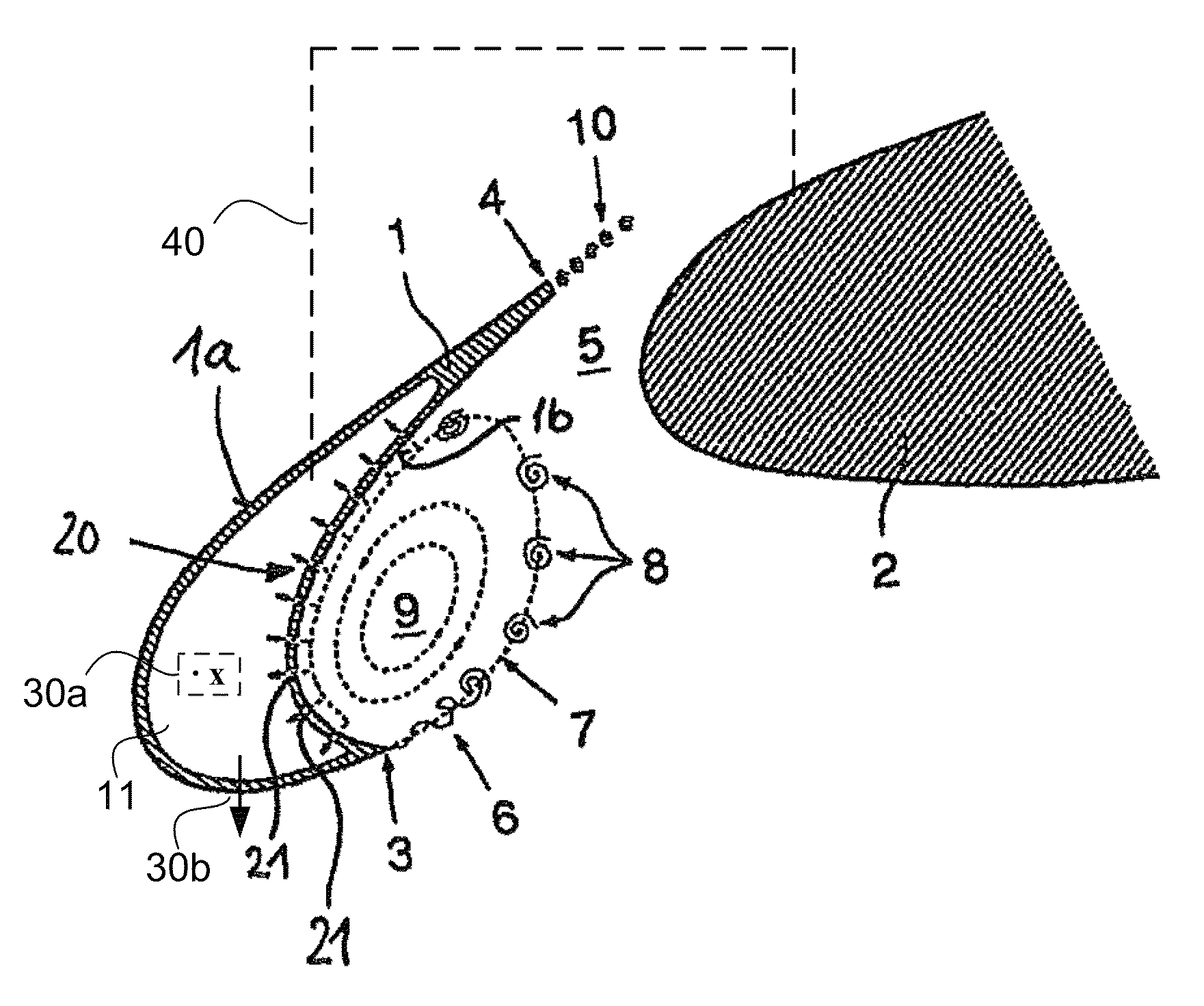
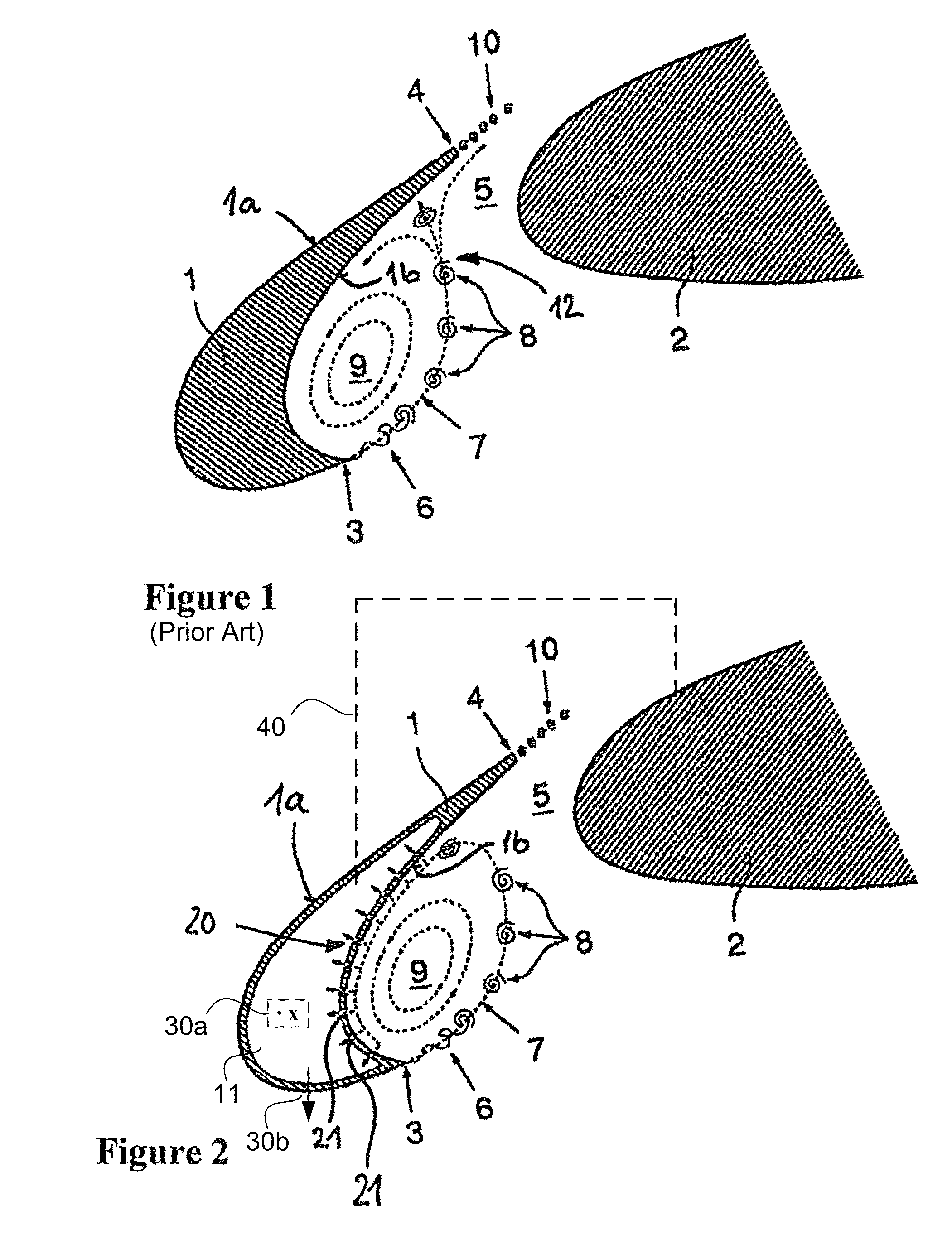
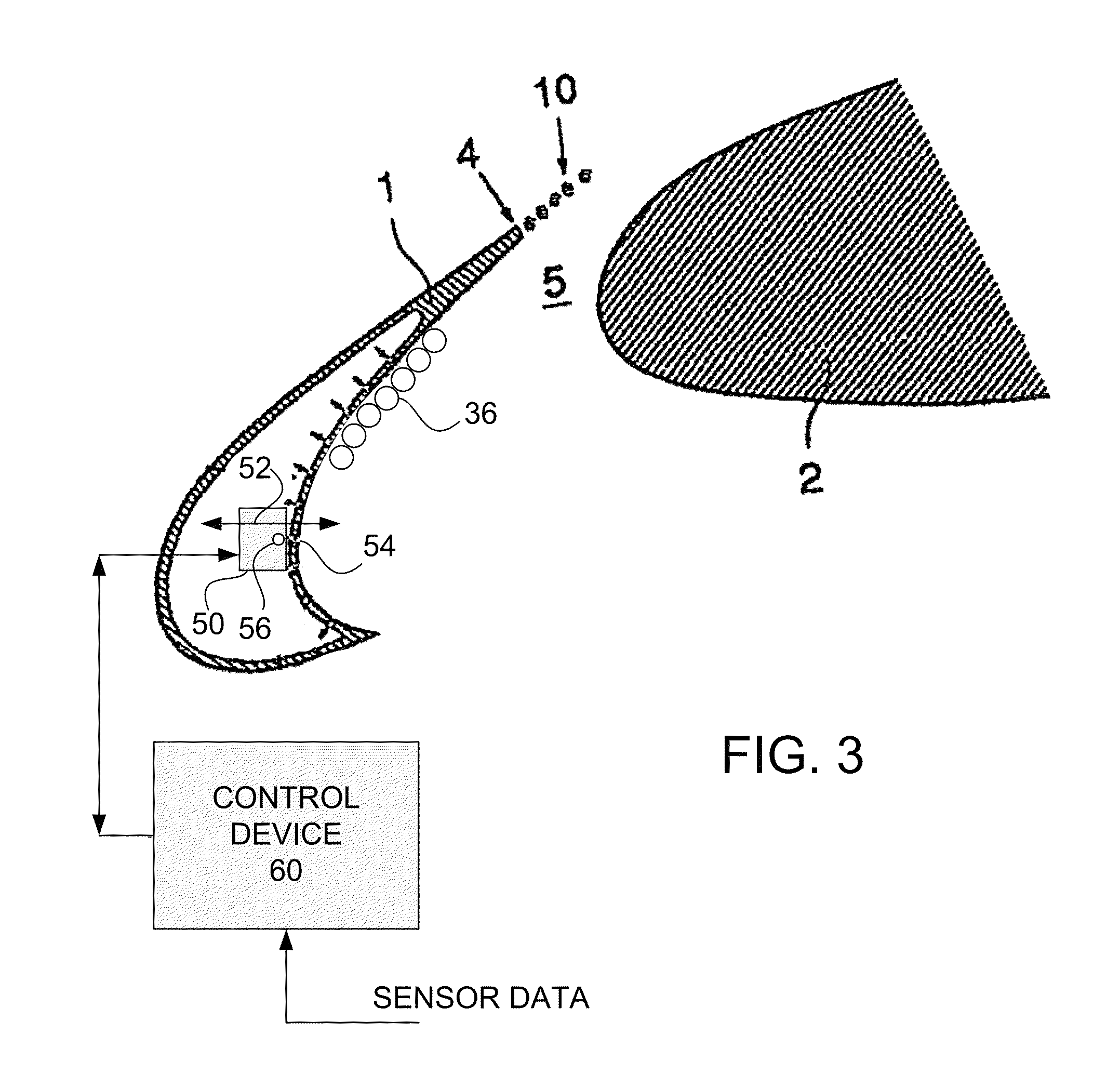
[0054]According to the invention a high-lift system for an aircraft with a main wing and a slat that by means of an adjustment device is adjustable relative to the main wing to various adjustment states is provided. The slat comprises a rear 1b that faces the main wing. Between the rear 1b and the main wing 2 there is a gap 5, whose size results from the adjustment state of the slat 1 relative to the main wing 2 and consequently in particular as a result of the distance between the slat 1 and the main wing 2. In the interior of the slat there is an air guidance channel 11 with at least one inlet 20 and an outlet. In this arrangement the inlet 20 is arranged at the rear 1b that faces the main wing so as to influence the airflow in the gap 5.

[0055]The void 11 in the slat 1 can be continuous or can be divided into several separate individual chambers, e.g. in order to make possible local adaptation of the suction-removal mass flow, controlled by way of different pressure conditions in ...


PUM


Abstract

A high-lift system for an aircraft with a main wing and a slat that by way of an adjustment device is adjustable relative to the main wing to various adjustment states, with a gap resulting between the rear of the slat, which rear faces the main wing, and the main wing, where the size of the gap results from the adjustment state of the slat relative to the main wing, where in the interior of the slat an air guidance channel with at least one inlet and an outlet is formed, where the inlet is arranged at the rear, which faces the main wing, in order to influence the airflow in the gap.

Description

CROSS REFERENCE TO RELATED APPLICATIONS[0001]This application claims priority to PCT Application No. PCT / EP2008 / 011042, filed Dec. 22, 2008; which claims priority to German Patent Application No. DE 10 2007 061 590.8, filed Dec. 20, 2007, and claims the benefit to U.S. Provisional Patent Application No. 61 / 015,217, filed Dec. 20, 2007, the entire disclosures of which applications are hereby incorporated by reference.BACKGROUND[0002]The invention relates to a high-lift system for an aircraft with a main wing and a slat that, by means of an adjustment device, can be adjusted relative to said main wing to various adjustment states, with said high-lift system comprising a device for influencing the airflow. By means of the device for influencing the airflow, in particular a reduction in the aerodynamic noise on slats of aircraft is achieved.[0003]Documents U.S. Pat. No. 3,363,859, EP 0230684A and DE746714C disclose a high-lift system for an aircraft with a main wing and a slat that by m...

Claims


Application Information

Patent Timeline
IPC IPC(8): B64C9/24B64C21/06
CPCB64C9/24B64C21/02Y02T50/166B64C2230/06B64C2230/04B64C2230/14Y02T50/10
Inventor KNACKE, THILOTHIELE, FRANK
Owner AIRBUS OPERATIONS GMBH
Learn More