
Electric railway power-supply system

a technology of electric railways and power supply systems, applied in the direction of final product manufacturing, electric devices, climate sustainability, etc., can solve the problems of large electric power consumption of electric vehicles, and achieve the effects of low manufacturing cost, excellent rapid charging and discharging characteristics, and energy saving

Inactive Publication Date: 2013-12-03
KAWASAKI HEAVY IND LTD
View PDF19 Cites 5 Cited by
  • Summary
  • Abstract
  • Description
  • Claims
  • Application Information

AI Technical Summary

Benefits of technology

The present invention provides an electric railway power-supply system with the following technical effects: installation area requirement low, fast charging and discharging, inexpensive manufacturing, energy saving, prevention of regeneration failure, peak cutting, power line voltage drop suppression. Additionally, the invention allows for sufficient extracting of electric vehicle running performance at remote locations, suppression of wasteful spending of running energy due to regeneration failure or power failure, and maintenance and servicing of the substation easy. Furthermore, the nickel hydrogen battery installed at the substation and the electric power storage and supply device containing the battery may be used in place of the substation for a short time, and the vehicle may be driven to a nearest railway station without stopping the auxiliary machines without stopping the vehicle.

Problems solved by technology

Specifically, the electric vehicle consumes a large amount of electric power in a short time at the time of acceleration.

Method used


Image

  • Electric railway power-supply system
  • Electric railway power-supply system
  • Electric railway power-supply system

Examples


first preferred embodiment

1. Configuration and Operation of Electric Railway Power-Supply System

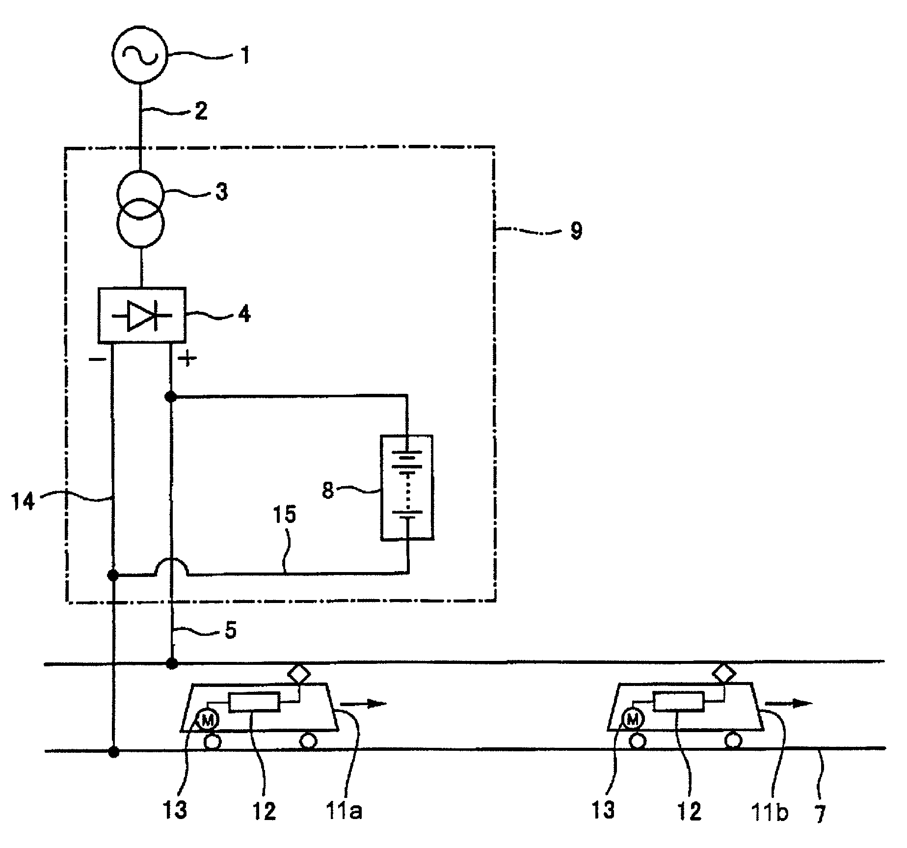
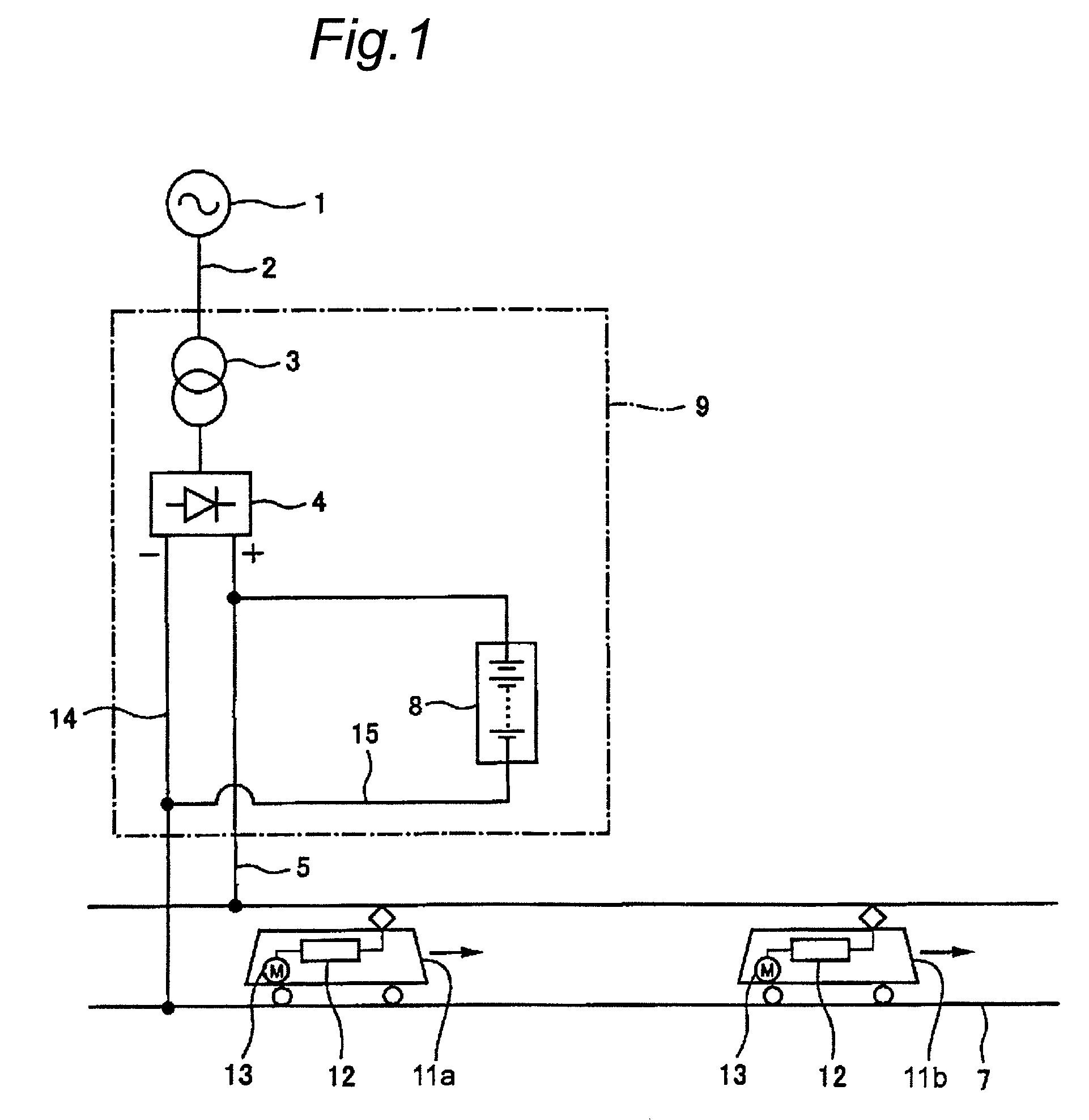
[0138]FIG. 1 is an outline structural diagram of an electric railway power-supply system provided with a nickel hydrogen battery in a first preferred embodiment of the invention.

[0139]As shown in FIG. 1, a substation for electric railway (hereinafter called “substation”) 9 includes a transformer 3 for receiving alternating-current power from an alternating-current power source 1 connected to an electric power system by way of an alternating-current power line 2, a rectifying device 4 connected to the transformer 3, and a nickel hydrogen battery (detail described below) 8 connected in parallel to the rectifying device 4. The rectifying device 4 has its positive side terminal connected to a feeder line 5, and negative side terminal to a return conductor 7 by way of a wiring 14. A nickel hydrogen battery 8 is directly coupled to the feeder line 5 and a wiring 15. More specifically, the nickel hydrogen battery 8 has i...

second preferred embodiment

1. Configuration and Operation of Electric Railway Power-Supply System

[0228]FIG. 16 is an outline structural diagram of an electric railway power-supply system in a second preferred embodiment of the invention. In the first preferred embodiment, the nickel hydrogen battery 8 was installed at the substation 9 for electric railway. By contrast, in the electric railway power-supply system in the second preferred embodiment of the invention, electric power storage and supply devices 10a and 10b including the nickel hydrogen battery 8 are installed at other positions than the substation 9, such as intermediate points between a substation and other substation for electric railway.

[0229]The battery module for composing the nickel hydrogen battery 8 to be used in the electric railway power-supply system in the second preferred embodiment of the invention may be the same as the battery module for composing the nickel hydrogen battery 8 used in the first preferred embodiment.

[0230]In the elec...


PUM

PropertyMeasurementUnit
voltageaaaaaaaaaa
voltageaaaaaaaaaa
internal resistanceaaaaaaaaaa

Abstract

To present an electric railway power-supply system not requiring vast area for installation, excellent in rapid charge-discharge characteristic, and low in manufacturing cost. At a substation 9 for electric railway having a transformer 3 for receiving power from an alternating-current power line 2, a rectifying device 4 connected to the transformer 3, and a feeder line 5 connected to the rectifying device 4, a nickel hydrogen battery 8 is provided as a direct-current supply facility, and the nickel hydrogen battery 8 is directly coupled to the feeder line 5.

Description

TECHNICAL FIELD[0001]The present invention relates to an electric railway power-supply system for supplying electric power to power lines for electric railway.BACKGROUND ART[0002]Generally, a substation for electric railway converts alternating-current power supplied from an electric power company or alternating-current power supplied from a power plant owned by an electric railway company into direct-current power, and supplies to feeder lines. The direct-current power supplied to the feeder lines passes through aerial power lines, and is supplied into electric vehicles by way of pantographs. Or the direct-current power is supplied from the feeder lines to the electric vehicles by way of a third rail. The electric vehicle supplies the provided electric power to a traction motor (rotary motor or linear motor) by way of an electric power control device mounted on the vehicle, and the electric energy is converted into a traction energy, and the vehicle is driven.[0003]The amount of en...

Claims


Application Information

Patent Timeline
Patent Type & Authority Patents(United States)
IPC IPC(8): H02J3/32B60M3/06H01M10/28H01M10/30H01M10/44H01M10/60H01M10/613H01M10/625H01M10/653H01M10/6555H01M10/6556H01M10/6563H01M10/6568H01M50/51H01M50/528H02J7/00
CPCB60L9/00B60M3/06H01M2/206H01M10/345H01M10/4207H01M10/5004H01M10/5032H01M10/5059H01M10/5067H01M10/5075B60L11/1801B60M3/02Y02T10/7088H01M10/5016Y02E60/124B60L2230/30Y02T10/7005Y02T90/12B60L2200/26H01M10/625H01M10/6563H01M10/647H01M10/6557H01M10/6567H01M10/613B60L50/53B60L53/53Y02E60/10Y02T10/7072Y02T10/70Y02P70/50H01M50/51
Inventor TSUTSUMI, KAZUOMATSUMURA, TAKAHIROTONDA, CHIYOHARUNISHIMURA, KAZUYAGOTO, FUMIYA
Owner KAWASAKI HEAVY IND LTD
Learn More