Thermal management smart valve with rupture detection and isolation

a technology of thermal management and smart valves, applied in the direction of fluid-tightness measurement, process and machine control, instruments, etc., can solve the problems of human intervention-based strategy drawbacks, extreme danger to personnel, and significant time and commitmen

Inactive Publication Date: 2013-12-03
THE UNITED STATES OF AMERICA AS REPRESENTED BY THE SECRETARY OF THE NAVY
View PDF3 Cites 30 Cited by
  • Summary
  • Abstract
  • Description
  • Claims
  • Application Information

AI Technical Summary

Benefits of technology

[0005]In view of the foregoing, it is an object of the present invention to provide an improved methodology for monitoring a co...

Problems solved by technology

However, there are drawbacks to this human intervention-based strategy.
Cooling system damage scenarios may demand significant time and commitment from ship personnel, and may pose ext...

Method used


Image

  • Thermal management smart valve with rupture detection and isolation
  • Thermal management smart valve with rupture detection and isolation
  • Thermal management smart valve with rupture detection and isolation

Examples


Embodiment Construction

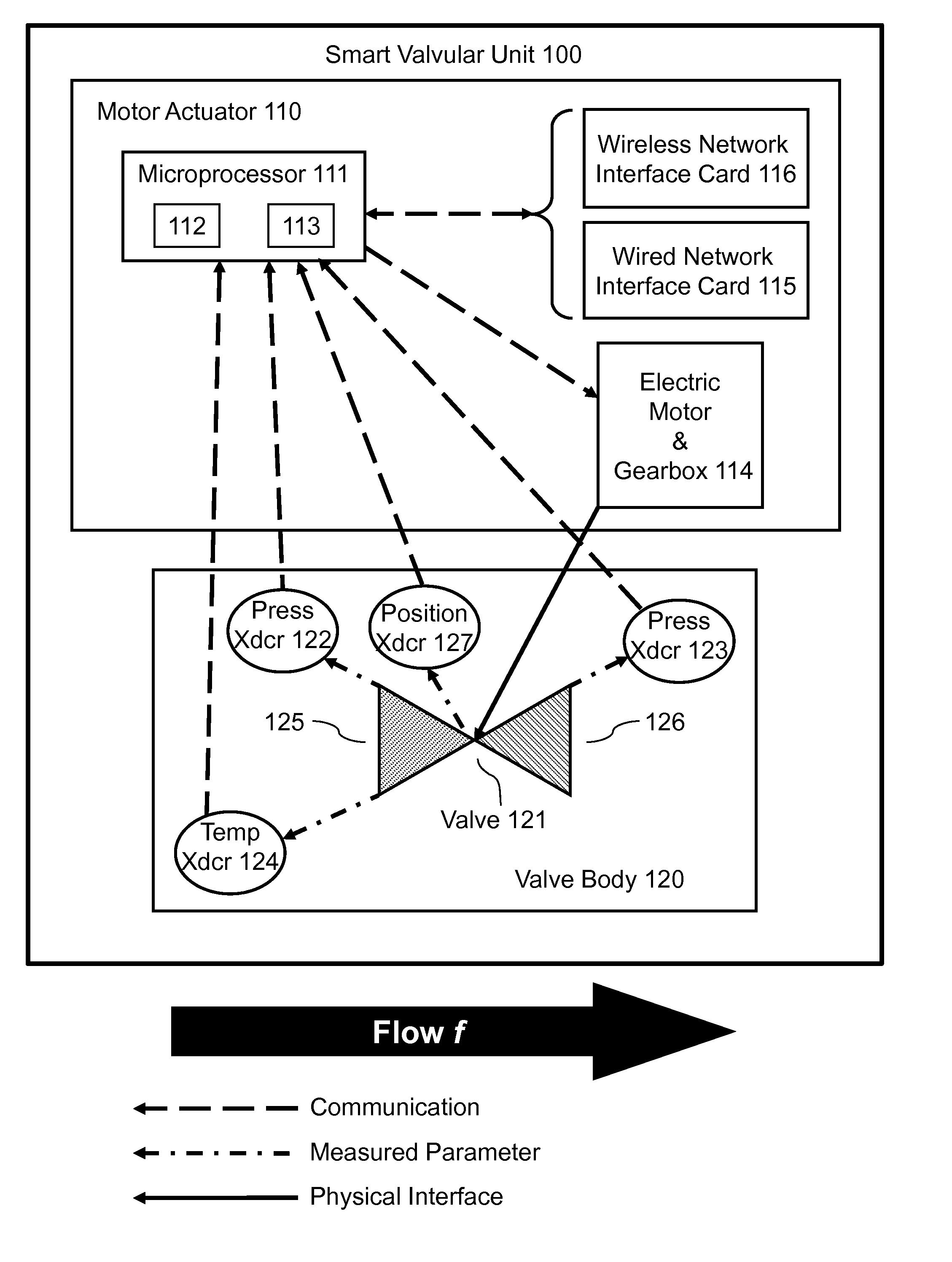
[0021]Referring now to FIG. 1, the present invention's inventive valvular unit 100 has two basic components, viz., a motor actuator component 110 and a valve body component 120. Inventive valvular unit 100 includes the following constituents of the motor actuator component 110: a computer (e.g., microprocessor) 111, which includes a processor 112 and a memory 113); a valve actuator (e.g., an electric motor-and-gearbox apparatus) 114; a wired network interface card 115 (for wired communication between inventive valvular unit 100 and other devices in a wired network); and, a wireless network interface card 116 (for wireless communication between inventive valvular unit 100 and other devices in a wireless network). Inventive valvular unit 100 further includes the following constituents of the valve body component 120: a two-way valve 121; water inlet pressure sensor 122; water outlet (discharge) pressure sensor 123; water temperature sensor 124; and, valve position sensor 127.

[0022]As ...


PUM


Abstract

The condition of a fluid piping system is monitored by multiple intercommunicative smart valves, each executing a computer algorithm that designates smart valves as critical or non-critical, compares measurement data versus simulation data, and makes decisions based on the critical-or-noncritical designations and the measurement-versus-simulation comparisons. Initial measurement-versus-simulation comparisons are made for downstream pressure, flow rate, and temperature. If a measurement-versus-simulation discrepancy is found in either the downstream pressure or the flow rate, then the algorithm compares a measurement rupture determinant versus a simulation rupture determinant; if a measurement-versus-simulation discrepancy is found in the rupture determinant, then the smart valve is closed. If a measurement-versus-simulation discrepancy is found in the temperature, then the smart valve, if non-critical, is closed; however, if the smart valve is critical, then the nearest upstream non-critical smart valve is closed. Any measurement-versus-simulation discrepancy results, at least, in an alarm or warning.

Description

BACKGROUND OF THE INVENTION[0001]The present invention relates to fluid conduction and fluid systems, more particularly to monitoring and controlling (regulating) fluid systems to detect and respond to failures such as pipe ruptures in the fluid systems.[0002]The United States Navy has developed electrically actuated valves and computer programming algorithms for effecting piping rupture detection. According to this Navy-developed technology, a “smart valve” measures differential fluid pressure across a valve in order to detect a pipe rupture. The Navy is implementing this pressure-based smart valve technology in the DDG-1000 and CG(X) classes of ships as part of a fire damage control system. See Donald D. Dalessandro and Leslie Spaulding, “Autonomic Fire Suppression System,”Seaframe, Naval Surface Warfare Center, Carderock Division, Volume 4, Issue 1, 2008, hereby incorporated herein by reference. See also, Lestina et al., U.S. Pat. No. 6,535,827 B1, issue date 18 Mar. 2003, entitl...

Claims


Application Information

Patent Timeline
IPC IPC(8): G05D7/00
CPCF17D5/00G01M3/00F16K37/0075F17D3/18F17D5/005
Inventor LONGO, DONALD R.DALESSANDRO, DONALD D.DONG, QINGFERRESE, FRANK T.ROACH, JOHN M.ZINK, MICHAEL G.
Owner THE UNITED STATES OF AMERICA AS REPRESENTED BY THE SECRETARY OF THE NAVY
Why Eureka
Try Eureka