
Piezoelectric actuator for an ultrasonic motor

Active Publication Date: 2013-12-10
PHYSIK INSTR PI
View PDF14 Cites 11 Cited by
  • Summary
  • Abstract
  • Description
  • Claims
  • Application Information

AI Technical Summary

Benefits of technology

The invention is about a piezoelectric actuator that is smaller, requires less voltage to operate, and is more stable and safe. It also has a simpler control and is less expensive to manufacture.

Problems solved by technology

The drawback of these actuators resides in the large dimensions thereof, which are defined by the dimensions of the metallic resonator.
Moreover, these actuators have a small volume of the piezoelectric active part as well as a great thickness of the piezoelectric element, which reduces the electromechanical coupling coefficient significantly so that the excitation voltage is considerably higher.
Such actuators additionally have a complicated structure, which requires an assembly by hand and increases the manufacturing costs.
The drawbacks of these actuators reside in their large dimensions, their complicated structure and the high manufacturing costs.
The drawback is that these actuators require a high excitation voltage.
Another significant disadvantage is the presence of a second longitudinal resonance which is within the range of the bending resonance.
This makes it harder to control these actuators, with the result that it is impossible to construct simple excitation circuits operated according to the self-excitation principle, whereof the excitation frequency is predetermined by the actuator itself.
This leads to a significant reduction of the thermal stability of the drive, reduces the operational safety of the actuators and renders the production more expensive.
This does not allow the configuration of an excitation circuit based on the self-excitation principle, the frequency of which is predetermined by the mechanical parameters of the actuator.
By this, the operating stability of the actuator is reduced, the structure of the excitation circuit is rendered more complicated and the drive system as a whole is rendered more expensive.

Method used


Image

  • Piezoelectric actuator for an ultrasonic motor
  • Piezoelectric actuator for an ultrasonic motor
  • Piezoelectric actuator for an ultrasonic motor

Examples


Embodiment Construction

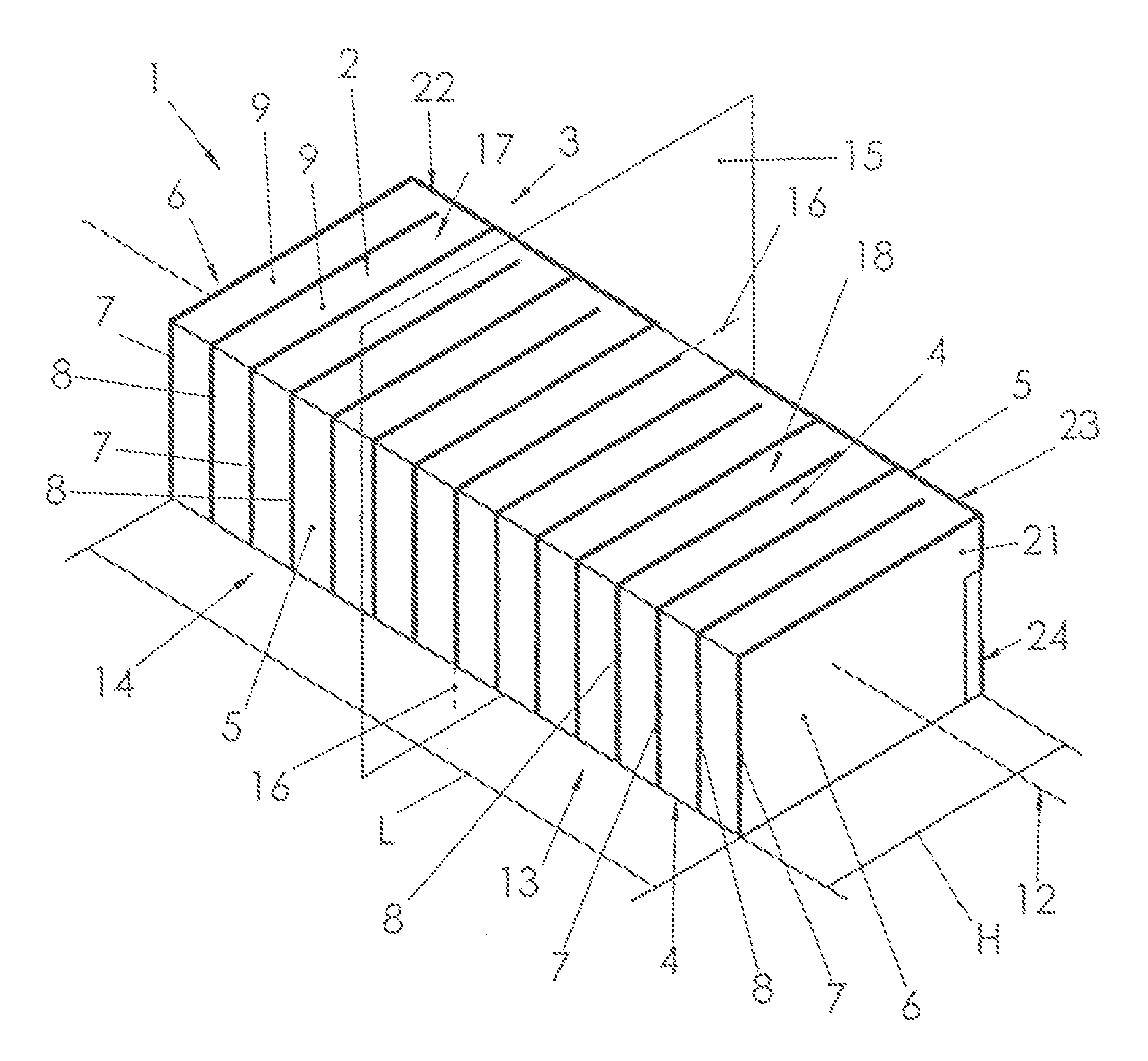
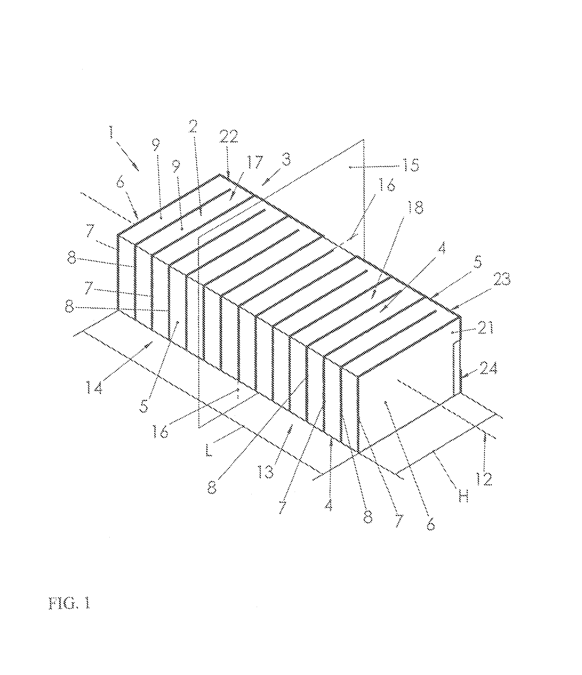
[0060]FIG. 1 shows a piezoelectric actuator 1 for ultrasonic motors. It is comprised of an acoustic oscillation resonator 2. The resonator 2 is formed as a rectangular piezoelectric plate 3 with two main surfaces 4, two side surfaces 5 and two end faces 6, with L being the plate length 3 along the side surface 5 and H being the height along the end face 6. The ratio of L / H of the actuator 1 as proposed is between 2 and 3.

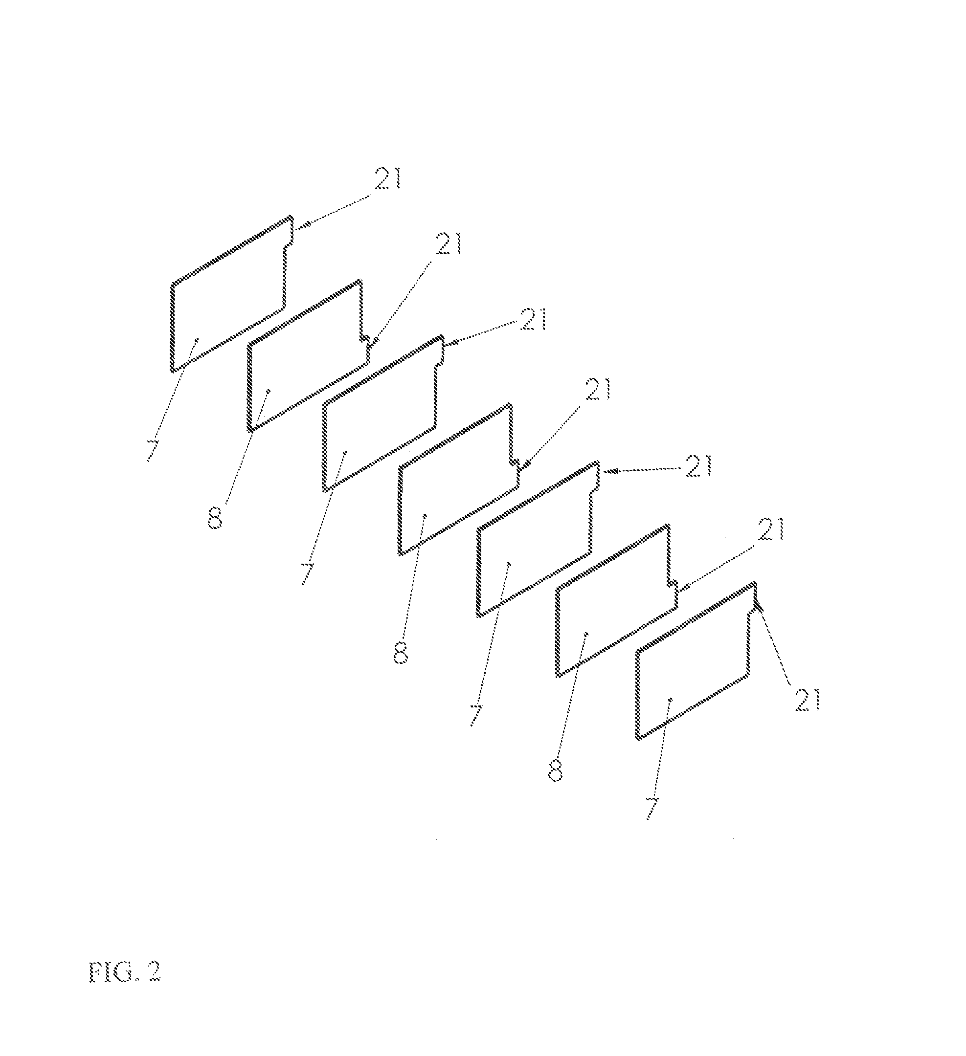
[0061]The piezoelectric plate 3 has a multilayer structure in its interior, which is formed of parallel layers of excitation electrodes 7 taking turns with parallel layers of common electrodes 8 (see FIG. 3) and layers of polarized piezoceramic 9 provided therebetween, the polarization vector extending perpendicularly with respect to the electrode surfaces 7 and 8, see arrows in FIG. 3, Position 10 and 11. The direction of the polarization vector coincides with that of the polarization axis of the piezoelectric plate 3, see dotted line 12, illustrated in FIG. 3 and ...


PUM


Abstract

A piezoelectric actuator, especially for an ultrasonic motor, includes an acoustic oscillation resonator, wherein the acoustic oscillation resonator is substantially formed as a rectangular piezoelectric plate with two main surfaces, two side surfaces and two end faces and has a multilayer structure in its interior which represents a layer of excitation electrodes taking turns with the layers of the common electrodes and the layers of polarized ceramic provided therebetween, with the polarization vector extending perpendicularly with respect to the surface of the electrodes, wherein all excitation electrodes are divided into two groups not connected to each other, which are disposed symmetrically with respect to the symmetry surface of the aforementioned plate, wherein this symmetry surface extends perpendicularly with respect to the main and side surfaces of the plate, namely through the center thereof.

Description

STATEMENT REGUARDING FEDERALLY SPONSORED RESERCH OR DEVELOPMENT[0001]Not ApplicableTHE NAMES OF THE PARTIES TO A JOINT RESERCH AGREEMENT[0002]Not ApplicableINCORPORATED-BY-REFERENCE OF MATERIAL SUBMITTED ON A COMPACT DISC[0003]Not ApplicableBACKGROUND OF THE INVENTION[0004](1). Field of the Invention[0005]The invention relates to piezoelectric actuators for rotary ultrasonic and linear motors. These can be employed for driving motors for linear and rotary motions. Moreover, they can be used for driving instrument racks, optical lenses, optical write and read heads as well as other similar devices requiring a high positioning accuracy, small dimensions of the drive system and low supply voltages.[0006](2). Description of Related Art[0007]Known are piezoelectric actuators for ultrasonic motors comprised of a metallic resonator for acoustic waves, with pasted-on lamellar piezoelectric elements, which excite acoustic waves in the resonator (see, inter alia, U.S. Pat. Nos. 5,665,918; 5,6...

Claims


Application Information

Patent Timeline
IPC IPC(8): H01L41/08
CPCH01L41/083H02N2/002H02N2/008H02N2/026H10N30/50
Inventor WISCHNEWSKIJ, WLADIMIRWISCHNEWSKIJ, ALEXEJ
Owner PHYSIK INSTR PI
Learn More