Radiation hardened motor drive stage

a technology of hardened motor drive and gate voltage, which is applied in the direction of pulse technique, dynamo-electric converter control, semiconductor/solid-state device details, etc., can solve the problems of electrical commutators exposed to various kinds of radiation damage, and achieve the effect of maximizing the magnitude of gate voltage signal, more robust response and higher signal magnitud

Inactive Publication Date: 2013-12-10
SUMMER STEVEN E
View PDF17 Cites 0 Cited by
  • Summary
  • Abstract
  • Description
  • Claims
  • Application Information

AI Technical Summary

Benefits of technology

[0009]A conventional, non-traditional hardened P-channel FET has a gate threshold voltage that also will shift more negatively as it is exposed to radiation. The initial threshold voltage will never go through a region where the FETs are uncontrollable and only go from a negative value to a more negative value. Therefore, conventional P channel FETs could have a more robust response to a total dose effect that unconventional N-channel FETs would have if the proper gate drive signal is provided.
[0010]The gate drive signal must be sufficiently high in magnitude to saturate the drain to source channel for either unconventional N-channel or P-channel types. The gate drive signal can not however be so high that it exceeds the gate to source breakdown voltage rating of the FET. It is important to maximize the magnitude of the gate voltage signal, because the higher the signal magnitude is, than the higher that the radiation dose for the FETs will be. It is important to implement a negative gate bias when placing the FET in the off mode. The negative bias compensates for the effect of trapped charges within the gate oxide, thus permitting the N-channel FET to switch on and off, despite negative shifts in the gate threshold voltage.

Problems solved by technology

In such environments, the electronic commutators are exposed to various kinds of radiation damage and in particular to ionizing radiation.

Method used


Image

  • Radiation hardened motor drive stage
  • Radiation hardened motor drive stage
  • Radiation hardened motor drive stage

Examples


Embodiment Construction

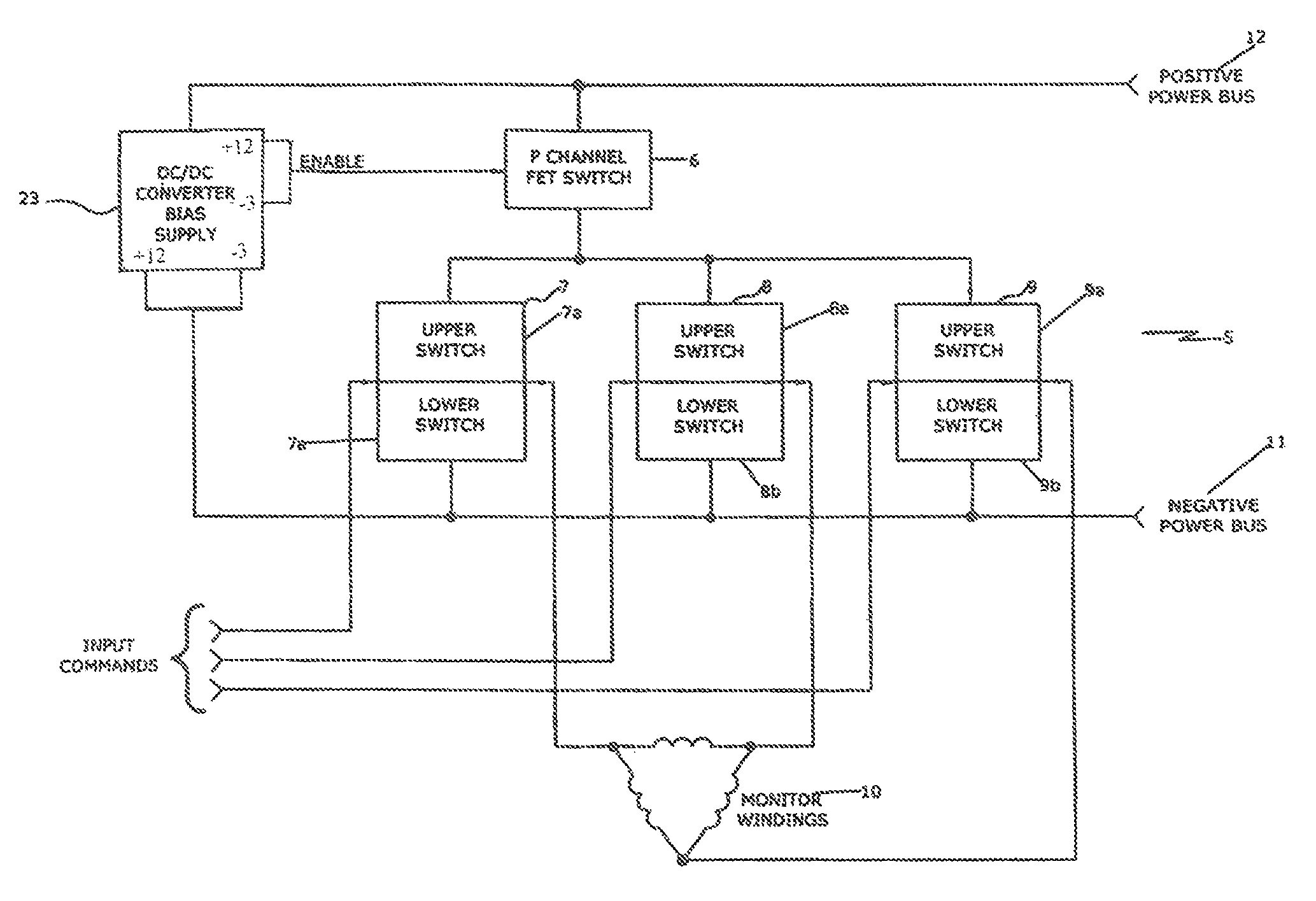
[0014]Referring now to the drawings of FIGS. 1 and 2, FIG. 1 shows a radiation hardened motor drive stage 5 that includes a P-channel FET switch 6 which feeds three (3) pairs, 7, 8 and 9 of upper 7a, 8a and 9a and lower switches 7a, 8b, and 9b blocks or legs, with the output of each pair of upper 7a, 8a and 9a and 7b, 8b and 9b blocks connected to a motor winding terminal 10. The upper switch blocks 7a, 8a and 9a are each connected to the output of the P-channel FET switch 6, while the lower switch blocks 7b, 8b and 9b are connected to the negative power bus 11.

[0015]In addition, the radiation hardened motor drive stage 5 also includes a DC-DC converter / bias supply 23. The DC-DC converter block 23 operates from the input power bus 12 and produces two pairs of isolated outputs. Each pair of isolated outputs produces a nominal voltage of +12 VDC and −3 VDC. The negative bias voltage 11 serves to control the ionizing radiation even when the gate threshold voltage drops below zero volts...


PUM


Abstract

A radiation hardened motor drive stage utilizes a non-radiation hardened P-channel FET switch. The radiation hardened motor drive stage includes a non-radiation hardened P-channel FET switch that is connected three (3) pairs of upper and lower switch blocks or legs wherein the output of each pair is connected to a motor winding switch terminal. The upper switch blocks or legs are connected the P-channel switch a. The lower switch block or legs are connected to a negative power bus. The negative power bus permits the N-channel FETS or IGTS within the switch blocks or legs exposed to ionized radiation to be controlled, even when their gate threshold voltage has dropped below zero volts.

Description

FIELD OF THE INVENTION[0001]The present invention relates to a motor drive state for brushless DC motors and stepper motors capable of tolerating the effect of a total ionizing radiation dose of between ranges of 1000 to 2000 Grays while using commercially available transistors that are not specifically radiation hardened. In particular, the present invention provides a cost effective motor drive stage capable of operating in a high ionizing radiation environment such as those employed in space satellites and particle accelerator applications.THE RELATED ART[0002]Motor drive stages are electronic switching devices that are powered by a DC power source. These motor drive stages apply voltage to motor windings in response to an external command. This voltage that is applied to the electronic motor communicators generates a torque that permits the motor to rotate. The windings are generally arranged in two or three stator phases.[0003]Motor drive stages are used for a variety of uses i...

Claims


Application Information

Patent Timeline
Patent Type & Authority Patents(United States)
IPC IPC(8): H02M3/335
CPCH03K17/22H03K17/6871H03K2017/0803H03K2217/0081
Inventor SUMMER, STEVEN E.
Owner SUMMER STEVEN E
Why Eureka
Try Eureka