Electrolysis system and method

a technology of electrolysis system and electrode, applied in the direction of electrolysis components, electrolysis organic production, separation processes, etc., can solve the problems of drop in electrolysis efficiency, leakage current flowing from the electrode to other areas, and clogging of the delivery pipe, so as to reduce the ohmic loss, improve the efficiency of electrolysis current, and achieve effective electrolysis

Inactive Publication Date: 2013-12-17
ASAHI GLASS CO LTD
View PDF19 Cites 4 Cited by
  • Summary
  • Abstract
  • Description
  • Claims
  • Application Information

AI Technical Summary

Benefits of technology

[0032]With the molten salt electrolysis apparatus according to the first aspect of the present invention, providing the electrodes including the first and second insulation members enables a suppression of a leakage current while reducing an ohmic loss, without causing any disturbances to the movements of electrolysis product gas and electrolysis product metal, thereby enabling the improvement in electrolysis current efficiency. In this case, further, providing the electrode frame enables a temperature of electrolyte to be adjusted in an electrolysis reaction region in the electrode frame, thereby making it possible to achieve an effective electrolysis.
[0033]With the molten salt electrolysis apparatus according to the second aspect of the present invention, further, gas is reliably generated at the anode surface portions of the electrodes and melt metal is reliably generated at the cathode surface portions with a specific gravity higher than that of melt electrolyte, enabling electrolysis at improved current efficiency.
[0034]With the molten salt electrolysis apparatus according to the third aspect of the present invention, furthermore, melt metal, generated at the cathode surface portions, is caused to reliably flow downward through the flow passages to the bottom portion of the electrolysis vessel. This reliably prevents electrolysis product gas and electrolysis product metal from contacting each other, thereby enabling electrolysis product metal to be reliably discharged to the outside of the electrodes.
[0035]With the molten salt electrolysis apparatus according to the fourth aspect of the present invention, moreover, melt metal, generated at the cathode surface portions, can be introduced from the inlet of the flow passages to the flow passages in a reliable manner. In addition, melt metal, generated at the cathode surface portions, can be caused to flow pass through the flow passages to reliably flow downward to the bottom portion of the electrolysis vessel.
[0036]With the molten salt electrolysis apparatus according to the fifth aspect of the present invention, besides, providing at least one of the chamfered corner portions and the cutout portions enables melt metal, generated at the cathode surface portions, to be reliably introduced into the flow passages from the inlet of the flow passages.
[0037]With the molten salt electrolysis apparatus according to the sixth aspect of the present invention, further, providing the protruding portions to at least one of the first and second insulation members enables the associated insulation members to be spaced in a further decreased distance than that between the associated electrode surface portions, enabling a further reduction in leakage current. In addition, a strong electrolyte current is generated on the anode surface portions, thereby enabling electrolysis product gas and electrolysis product metal to be separated from each other in a more reliable manner.

Problems solved by technology

This results in the production of zinc chloride with a yield about ten times that of silicon in yield, causing a serious issue to arise with the establishment of a collection processing method for zinc chloride.
However, a vapor pressure of zinc chloride increases up to a level of about 0.05 atm and chlorine gas is generated accompanied by the occurrence of a large amount of mist, resulting in a tendency of causing a phenomenon to occur with the clogging of delivery pipes unless otherwise addressed.
With the use of such bipolar type electrodes, however, if a space between the electrodes is caused to decrease with a view to decreasing an ohmic loss of a region around the electrodes and increasing electrolysis efficiency, a leakage current inevitably flows from the electrodes to other areas.
This results in a tendency of causing a drop in electrolysis efficiency and hence, it is recognized that there is a room for improvement in respect of such a phenomenon.

Method used


Image

  • Electrolysis system and method
  • Electrolysis system and method
  • Electrolysis system and method

Examples


first modified example

[0136]An electrode unit 41 of the first modified example of the present embodiment shown in FIG. 4 differs from the structure of the electrode unit shown in FIG. 3 mainly in that the lower insulation members 10 have discharge flow passages 16, respectively, each extending in the vertical direction.

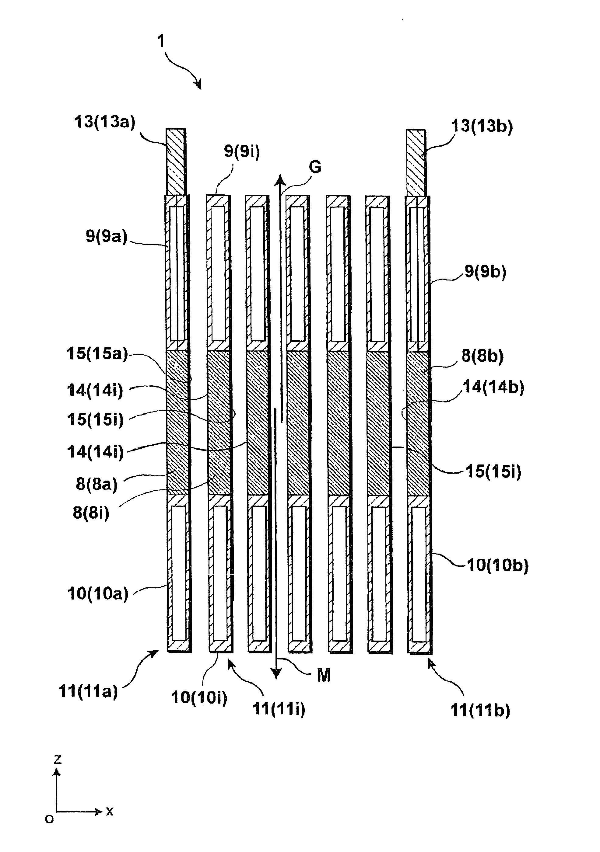
[0137]As set forth above, upon electrolysis reaction, electrolysis product gas G is generated at the anode surface portions 14 and moves upward whereas melt metal M in the form of electrolysis product metal is generated at the cathode surface portions and moves downward. Upon further study, if an attempt is made to mount the insulation members 9 and 10 on the electrodes 8, respectively, and allow the electrodes 8 to be spaced from each other with a progressively decreasing distance, an ohmic loss and a leakage current decrease with a resultant decrease in electrolysis voltage. However, resulting melt metal M tends to adhere to surfaces of the cathode surface portions 15 at lower ends there...

second modified example

[0143]An electrode unit 51 of a second modified example of the present embodiment, shown in FIG. 5, differs in structure from the electrode unit 41 of the first modified example, shown in FIG. 4, mainly in that the upper insulation members 9 have one sides formed with protruding portions 9p, respectively, which jut toward the proximal neighboring upper insulation members 9 so as to protrude with respect to the cathode surface portions 15 of the electrodes 8, respectively. In addition, the end electrode 8b has no cathode surface portion 15 and hence, the protruding portion 9p can be omitted from the upper insulation member 9b associated with the end electrode 8b. Of course, further, such protruding portions 9p of the upper insulation members 9 may be provided in the electrode unit 1 shown in FIG. 3.

[0144]With such a structure of the present modified example, like the structure determined in the lower insulation members 10 of the first modified example, a distance d′ between the upper...

third modified example

[0146]An electrode unit 61 of a third modified example of the present embodiment, shown in FIG. 6, differs in structure from the electrode unit 51 of the second modified example, shown in FIG. 5, mainly in that the electrodes 8 and the upper and lower insulation members 9 and 10, associated with the electrodes 8, respectively, are inclined by an angle θ with respect to the vertical direction such that the anode surface portions face downward and the cathode surface portions face upward. In addition, such inclining placements of the electrodes 8 may be applied to the electrode units 1 or 41 shown in FIG. 3 or FIG. 4.

[0147]With such a structure, slightly inclining the cathode surface portions 15 of the electrodes 8 so as to face upward enables electrolysis product gas G and electrolysis product metal M to be strongly constrained toward the anode surface portions 14 and the cathode surface portions 15, respectively. That is, anode product gas G is subjected to a force acting upward due...


PUM

PropertyMeasurementUnit
melting pointaaaaaaaaaa

Abstract

A molten salt electrolysis apparatus and a molten metal electrolyzing method using such a device are disclosed having an electrolysis vessel (4) accommodating melt electrolyte including melt metal chloride, and an electrode unit (1) having electrically conductive electrodes (8), first insulation members (9) covering upper end surfaces of the electrodes and fixed thereto while extending upward from the upper end surfaces, second insulation members (10) covering lower end surfaces of the electrodes and fixed thereto while extending downward from the lower end surfaces, and an electrode frame (12) composed of an insulating body surrounding the electrodes, the electrode unit being immersed in the melt electrolyte.

Description

TECHNICAL FIELD[0001]The present invention relates to an electrolysis apparatus and its related method for melt electrolyte and more particularly, to an electrolysis apparatus and its related method of electrolyzing molten metal chloride to obtain gas from an anode and melt metal from a cathode, respectively.BACKGROUND ART[0002]In recent years, a method of directly electrolyzing metal chloride to obtain metal and chlorine has heretofore been proposed. Unlike a production method with electrolysis conducted using an aqueous solution containing metal chloride, such a production method has characteristics of obtaining chlorine with high purity as high as 100% and metal with high purity. Thus, such a production method can be used not only for applications to the production of metal but also for collecting reduction metal used when metal is obtained from metal chloride.[0003]More particularly, as examples of metals obtained from metal chloride, alkali metals, such as sodium, and aluminum ...

Claims


Application Information

Patent Timeline
Patent Type & Authority Patents(United States)
IPC IPC(8): C25C3/04C25C7/02C25C7/04
CPCC22B5/02C22B5/04C22B19/20C22B61/00C25B1/26C25C3/34C25C7/005C25C7/00C25C7/08
Inventor SHIMAMUNE, TAKAYUKITAKEUCHI, YOSHINORI
Owner ASAHI GLASS CO LTD
Why Eureka
Try Eureka