Micro-combustion power system with dual path counter-flow system

a technology of counter-flow and micro-combustion power supply, which is applied in the direction of thermoelectric devices, mechanical devices, machines/engines, etc., can solve the problems of power consumption in existing micro-combustion power supply, ten times improvement of current battery energy density, etc., and achieve the effect of better managing the thermal/cooling issues of the device during operation

Inactive Publication Date: 2013-12-24
IRVINE SENSORS +1
View PDF19 Cites 9 Cited by
  • Summary
  • Abstract
  • Description
  • Claims
  • Application Information

AI Technical Summary

Benefits of technology

[0022]A novel element of the invention relates to the opposing configuration and opposing flow path directions of the respective flow path volumes. In this embodiment, the pre-heating heat exchange structure in the first flow path volume and the opposing post-combustion heat exchange structure are comprised of a shared, thermally conductive

Problems solved by technology

Given this high energy content, even a modest energy conversion efficiency of 10% results in potentially a ten times improvement in current battery energy density.
One of the main drawbacks in the

Method used


Image

  • Micro-combustion power system with dual path counter-flow system
  • Micro-combustion power system with dual path counter-flow system
  • Micro-combustion power system with dual path counter-flow system

Examples


Embodiment Construction

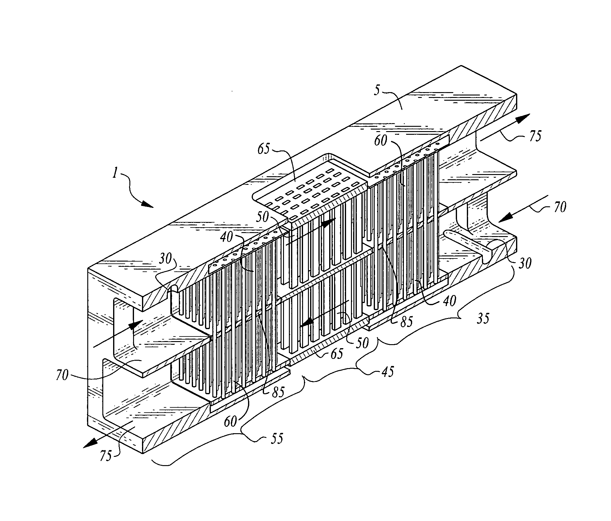
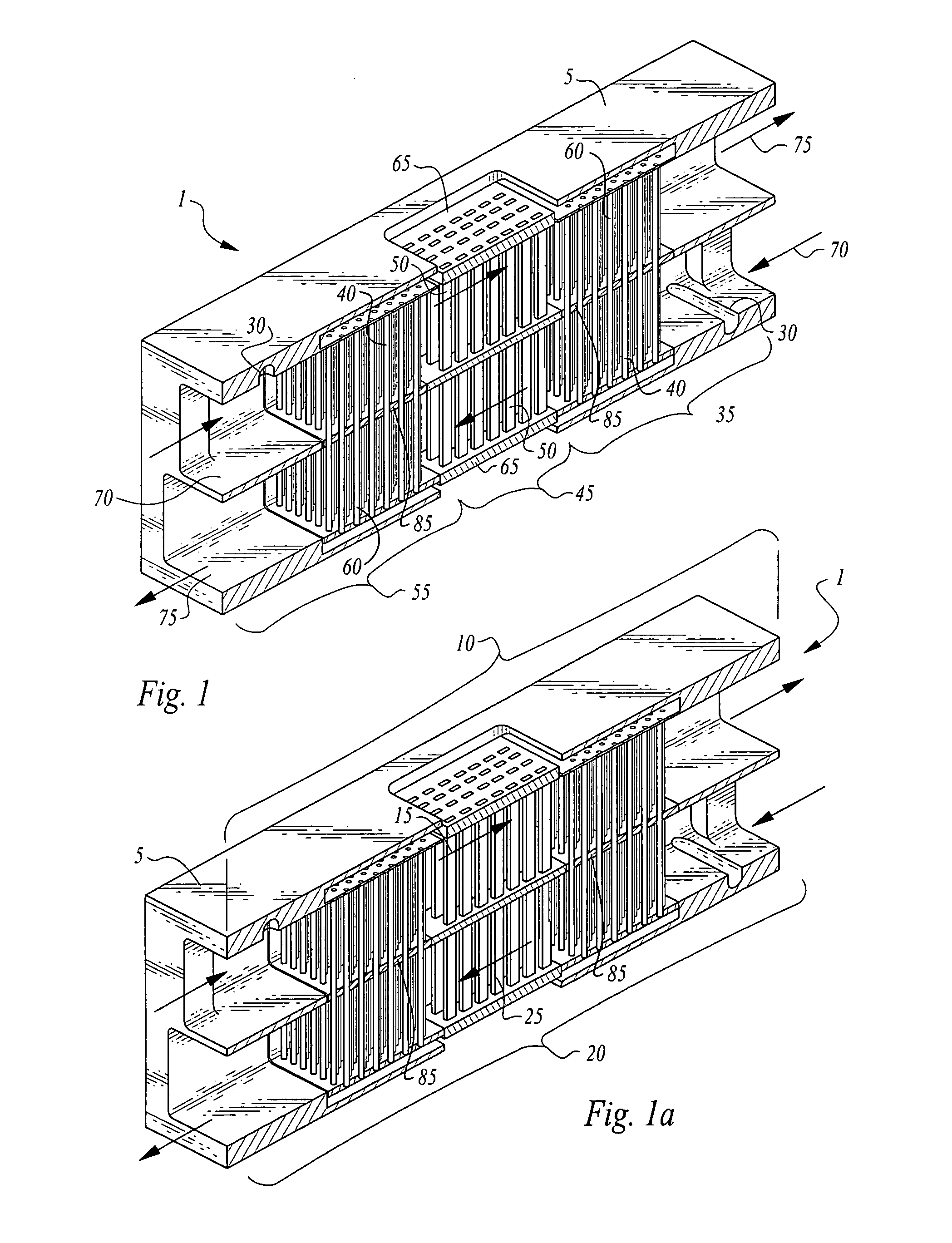
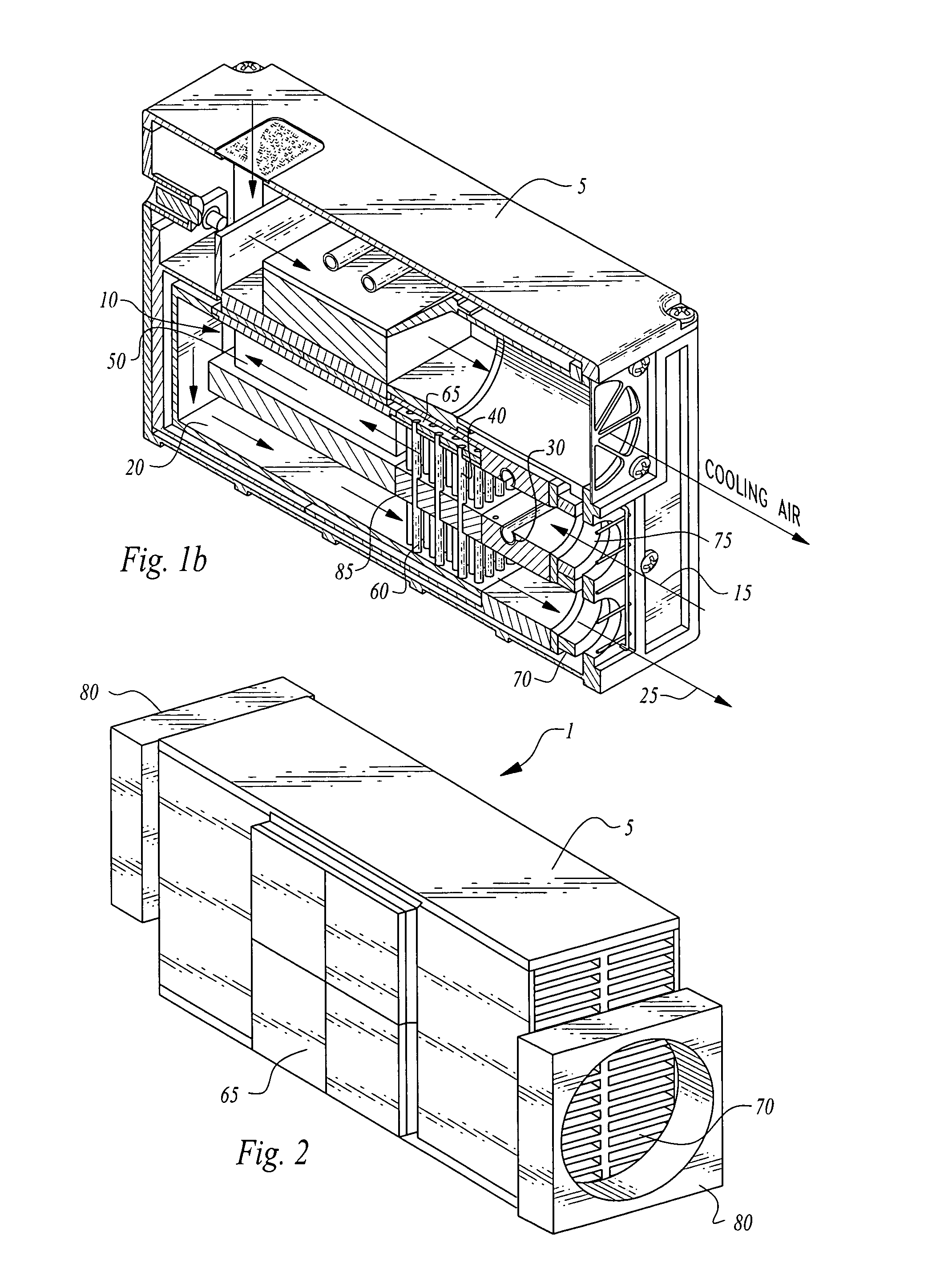
[0029]Turning now to the figures wherein like numerals define like elements among the several views, FIGS. 1, 1a, 2 and 3 illustrate a preferred embodiment of the dual path counter-flow micro-combustion power system 1 of the invention.

[0030]As seen in FIGS. 1 and 1a, micro-combustion power system 1 comprises a housing 5. Housing 5 comprises a first flow path volume 10 having a first flow path direction 15 and a second flow path volume 20 having a second flow path direction 25 opposing said first flow path direction 15.

[0031]Each of said flow path volumes comprises fuel valving means 30, a pre-heating volume, 35, a pre-heating heat exchange structure 40, a combustion volume 45, combustion means 50, shown as a finned element herein, a post-combustion volume 55, a post-combustion heat exchange structure 60, at least one thermoelectric generator means 65, an inlet port 70, an outlet port 75, air pressurization means 80 and insulating heat exchange frame means 85.

[0032]In a preferred emb...


PUM


Abstract

A micro-combustion power system is disclosed. The invention is comprised of a housing that further comprises two flow path volumes, each having generally opposing flow path directions and each generally having opposing configurations.
Each flow path volume comprises a pre-heating volume having at least one pre-heating heat exchange structure. Each flow path volume further comprises a combustion volume having a combustion means or structure such as a catalytic material disposed therein Further, each flow path volume comprise a post-combustion volume having at least one post-combustion heat exchange structure.
One or more thermoelectric generator means is in thermal communication with at least one of the combustion volumes whereby thermal energy generated by an air/fuel catalytic reaction in the combustion volume is transferred to the thermoelectric generator to convert same to electrical energy for use by an external circuit.
A novel element of the invention relates to the opposing configuration and opposing flow path directions of the respective flow path volumes. The pre-heating heat exchange structure in the first flow path volume and the opposing post-combustion heat exchange structure are comprised of a shared, thermally conductive structure and material. In this embodiment, waste heat from the exhaust gas in the post-combustion chamber is thermally transferred to the opposing pre-heating volume to heat the air/fuel mixture therein to a suitable pre-combustion temperature to take advantage of waste heat while better managing thermal/cooling issues of the device during operation.

Description

CROSS-REFERENCE TO RELATED APPLICATIONS[0001]This application claims the benefit of U.S. Provisional Patent Application No. 61 / 191,533, filed on Sep. 9, 2008 entitled “Micro-combustion Power System with Dual Counter Flow System” pursuant to 35 USC 119, which application is incorporated fully herein by reference.STATEMENT REGARDING FEDERALLY SPONSORED RESEARCH AND DEVELOPMENT[0002]This invention was made with Government support under Contract No. FA-8651-06-M-0180 awarded by the United States Air Force.[0003]The Government has certain rights in the invention.FIELD OF THE INVENTION[0004]The invention relates generally to the field of micro-combustion electrical power systems. More specifically, the invention relates to MEMS-scale electrical power systems that utilize a combustible fuel to produce electrical power using a thermoelectric generator element.BACKGROUND OF THE INVENTION[0005]Mobile electronic devices are common in consumer, industrial and military environments. Due to their...

Claims


Application Information

Patent Timeline
IPC IPC(8): H01L35/32
CPCH01L35/32H01L35/30H10N10/17H10N10/13
Inventor HSU, YINGSAPIR, ITZHAKRONNEY, PAULSNYDER, G. JEFFREY
Owner IRVINE SENSORS
Why Eureka
Try Eureka