PON system and redundancy method
a technology of passive optical network and redundancy method, which is applied in the field of pon system and redundancy method, can solve the problems of communication disconnection and large number of service subscribers, and achieve the effect of high reliability and cost suppression
- Summary
- Abstract
- Description
- Claims
- Application Information
AI Technical Summary
Benefits of technology
Problems solved by technology
Method used
Image

Examples
first embodiment
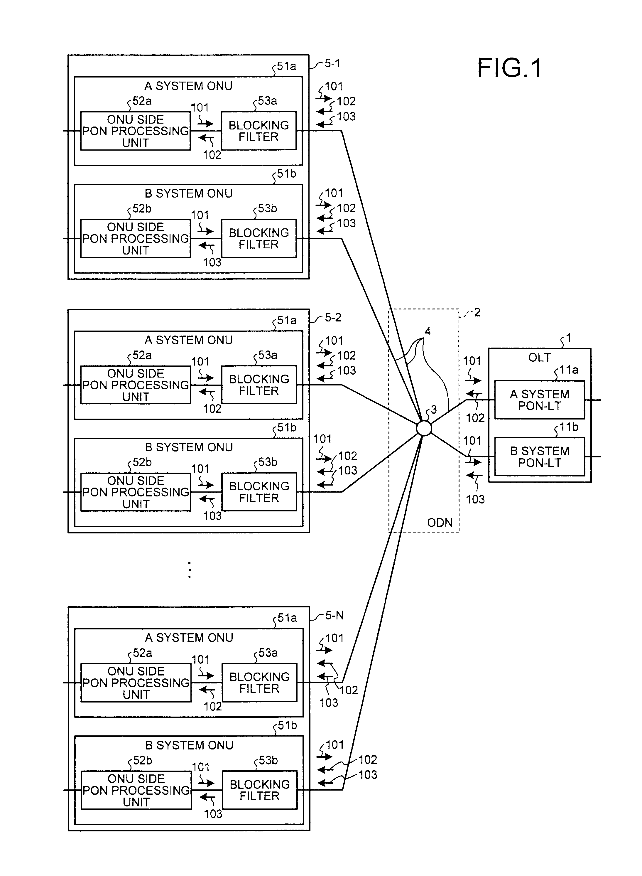
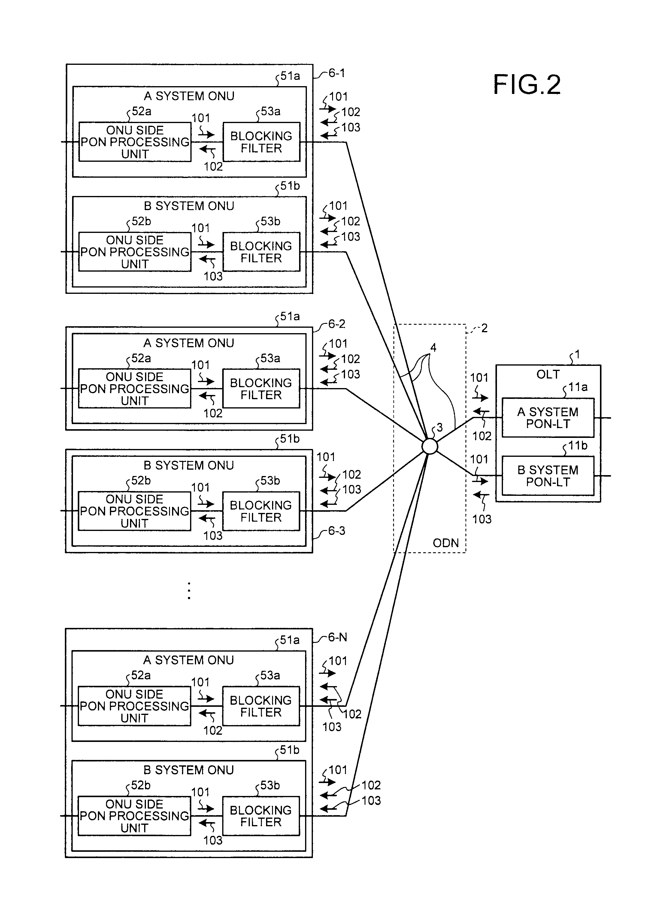
[0040]FIG. 1 is a diagram of a configuration example of a first embodiment of the PON system according to the present invention. As shown in FIG. 1, the PON system according to this embodiment includes an OLT 1, an ODN (Optical Distribution Network) 2, a splitter 3 which is a 2:M optical splitter and present in the ODN 2, subscriber home apparatuses 5-1 to 5-N set in the same subscriber home, and an optical fiber 4 that connects the OLT and the ODN and connects the subscriber home apparatuses 5-1 to 5-N and the ODN.
[0041]In this embodiment, a group of apparatuses having the same function are set in a home of a subscriber where redundancy is carried out, and the subscriber home apparatuses 5-2 to 5-N have a configuration same as that of the subscriber home apparatus 5-1. The subscriber home apparatus 5-1 includes two systems of ONUs; an A system ONU 51a and a B system ONU 51b. The A system ONU 51a includes an ONU side PON processing unit 52a that performs termination processing for u...
second embodiment
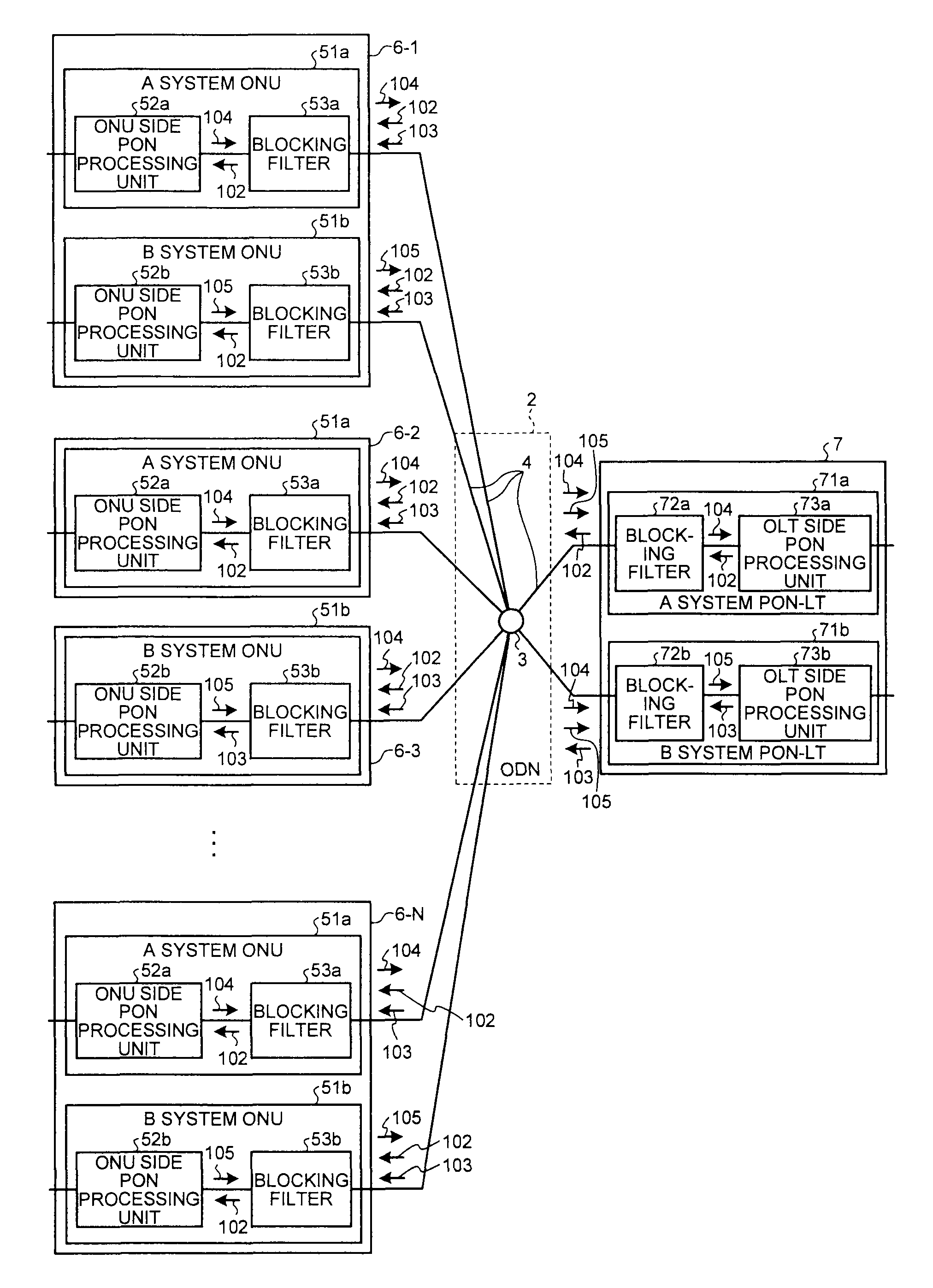
[0059]FIG. 4 is a diagram of a configuration example of a second embodiment of the PON system according to the present invention. The configuration of the PON system according to this embodiment is the same as that of the PON system according to the first embodiment except that the OLT 1 is replaced with an OLT 7. Components having functions same as those in the first embodiment are denoted by the same reference numerals and signs and explanation of the components is omitted.
[0060]The OLT 7 includes an A system PON-LT 71a and a B system PON-LT 71b. The A system PON-LT 71a includes a blocking filter 72a that blocks user data other than user data having a specific wavelength (a wavelength corresponding to the A system) and an OLT side PON processing unit 73a that performs termination processing for the user data. The B system PON-LT 71b includes a blocking filter 72b that blocks user data other than user data having a specific wavelength (a wavelength corresponding to the B system) an...
third embodiment
[0064]FIG. 5 is a diagram of a configuration example of a third embodiment of the PON system according to the present invention. The PON system according to this embodiment is the same as the PON system according to the first embodiment except that an L2SW (layer 2 switch) 8 connected to the OLT 1 and L2SWs 9-i connected to subscriber home apparatuses 6-i (i=1 to N) are added to the PON system explained with reference to FIG. 2 in the first embodiment. Components having functions same as those in the first embodiment are denoted by the same reference numerals and signs and explanation of the components is omitted.
[0065]In the first embodiment and the second embodiment, the control frame such as Ethernet (registered trademark) OAM is transmitted and received between the OLT 1 and the ONUs 5-1 to 5-N (or the ONUs 6-1 to 6-N). Alternatively, in this embodiment, an L2SW 8 on a higher level side is set as a terminal end of the control frame. An L2SW 7 according to this embodiment is conn...
PUM
 Abstract
Description
Claims
Application Information
 - R&D
- Intellectual Property
- Life Sciences
- Materials
- Tech Scout
- Unparalleled Data Quality
- Higher Quality Content
- 60% Fewer Hallucinations
Browse by: Latest US Patents, China's latest patents, Technical Efficacy Thesaurus, Application Domain, Technology Topic, Popular Technical Reports.
© 2025 PatSnap. All rights reserved.Legal|Privacy policy|Modern Slavery Act Transparency Statement|Sitemap|About US| Contact US: help@patsnap.com