Engine combustion control via fuel reactivity stratification

a fuel reactivity and engine technology, applied in the direction of electric control, machines/engines, mechanical equipment, etc., can solve the problem of low combustion ra

Active Publication Date: 2013-12-31
WISCONSIN ALUMNI RES FOUND
View PDF33 Cites 17 Cited by
  • Summary
  • Abstract
  • Description
  • Claims
  • Application Information

AI Technical Summary

Benefits of technology

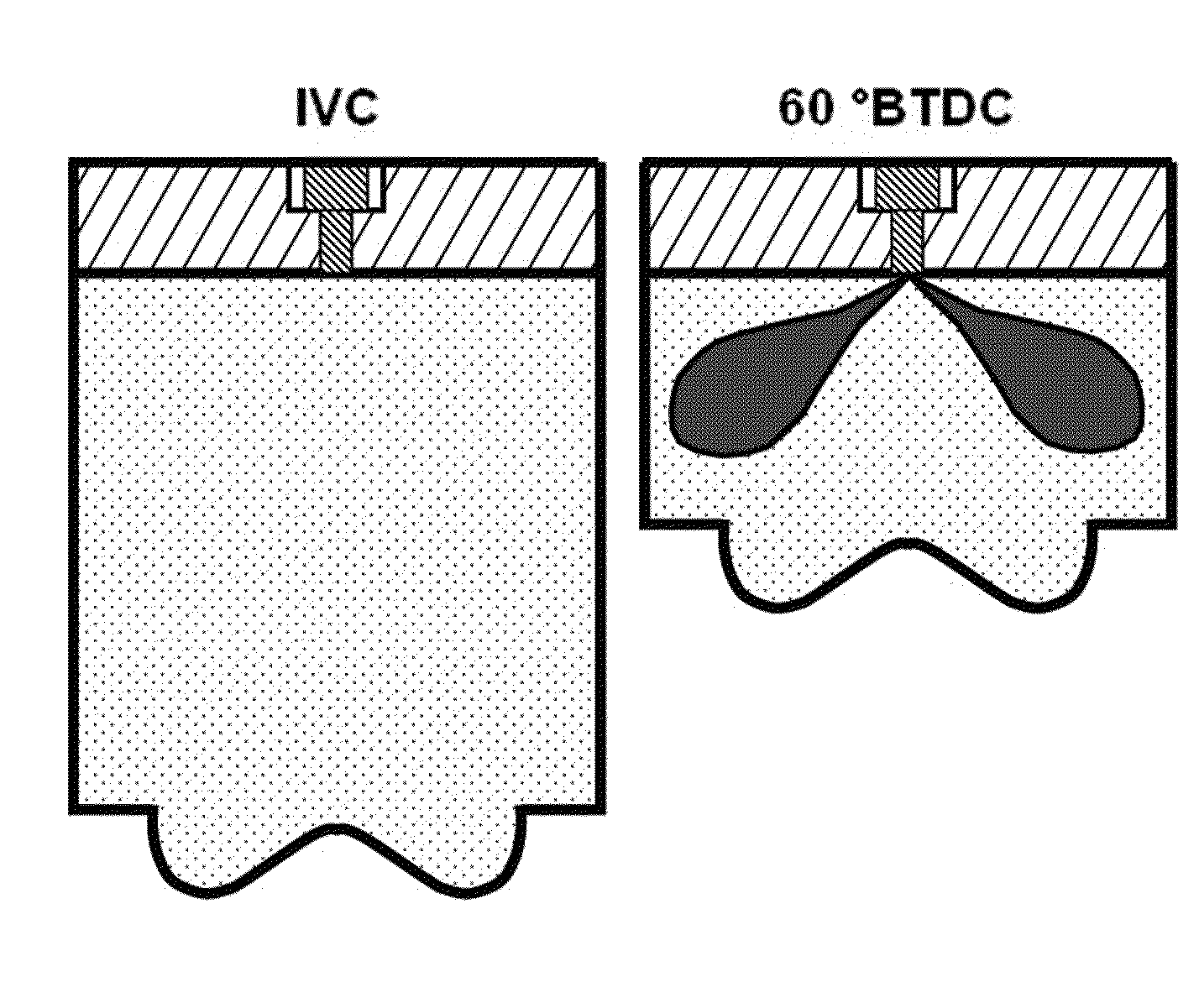
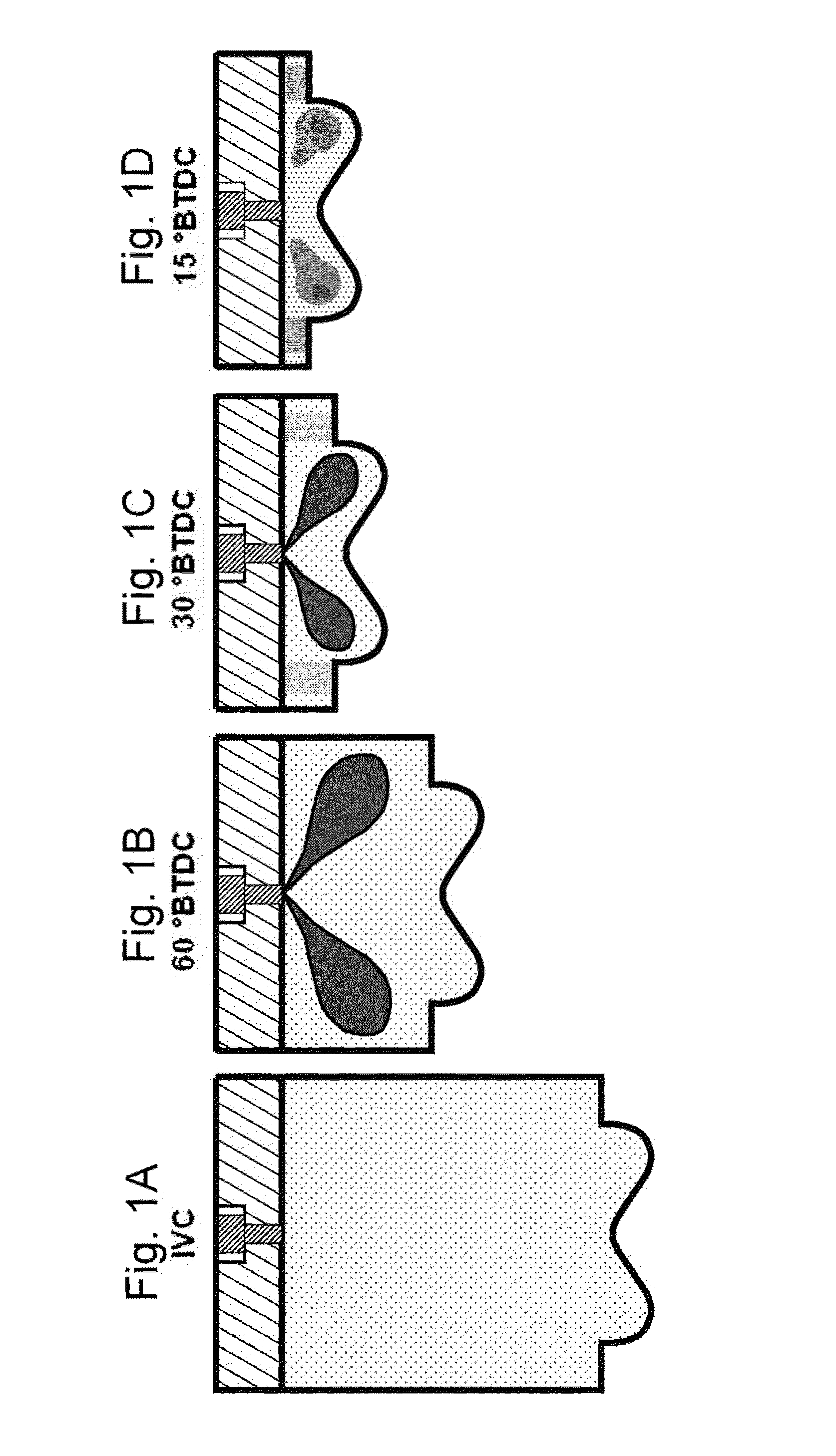
[0012]In a diesel (compression ignition) engine, an initial fuel charge having a first reactivity—with the term “reactivity” generally corresponding to cetane number, but being discussed in greater detail elsewhere in this document—is supplied to the combustion chamber during the intake and / or compression stroke, preferably sufficiently early that the initial fuel charge is highly premixed with the air in the combustion chamber during a major portion of the compression stroke. One or more subsequent fuel charges of different reactivity are thereafter supplied to the combustion chamber in such a manner that a stratified distribution of fuel reactivity results within the combustion chamber, with distinct regions of higher and lower fuel reactivity. More specifically, the later different-reactivity charges are timed and otherwise designed to distribute the different-reactivity charges—which will be introduced into a preferably highly premixed “matrix” of air and first-reactivity fuel—in such a manner that the reactivity gradient within the combustion chamber provides a desired combustion start time and rate (a time / rate that results in controlled heat release resulting in superior work input to the piston), while deterring rapid pressure increases and high temperatures (which promote NOx production and reduce fuel economy), and while completely burning all (or nearly all) fuel within the combustion chamber to reduce unburnt hydrocarbons. Combustion tends to begin in one or more regions of highest reactivity (these regions being generated via the introduction of the higher-reactivity material), and spreads therefrom via volumetric energy release and / or flame propagation until all fuel from all charges is consumed. Thus, tailoring of the reactivity distribution within the combustion chamber can allow tailoring of the nature of the combustion process. Greater stratification / gradation in reactivity tends to result in a lower combustion rate. Conversely, lower stratification / gradation in reactivity (greater uniformity in reactivity throughout the combustion chamber) tends to result in a higher combustion rate, since each location within the chamber has an approximately equal chance of igniting first, and those that do not ignite first will be rapidly ignited by their neighbors.
[0018]Basically the same combustion mechanism results if the reactivities of the charges of FIGS. 1A-1D are reversed, i.e., if one or more initial higher-reactivity charges are followed by one or more subsequent lower-reactivity charges: ignition begins in the higher-reactivity regions and propagates to the lower-reactivity regions. The start and duration of combustion can be controlled by the timings and amounts of the fuel charges, which affect the degree of stratification attained. For optimal work output, it is desirable that the fuel charges are supplied to the combustion chamber to attain peak cylinder pressure at or after Top Dead Center (TDC), more preferably between TDC and 20 degrees ATDC (After TDC), and most preferably between 5 and 15 degrees ATDC. In similar respects, CA50 (i.e., 50% of the total fuel mass burned) preferably occurs between approximately 0 to 10 degrees ATDC. It is also useful to supply the fuel charges in such a manner that the rate of pressure rise is no greater than 10 bar per degree of crank angle rotation, since greater pressure rise can generate unwanted noise and more rapid engine wear, and also promotes higher temperatures (and thus increased fuel consumption owing to heat transfer losses, as well as NOx production).
[0019]Use of the foregoing methodology tends to result in much lower peak combustion temperatures—as much as 40% lower—than in conventional diesel engines, owing to the increased control over the combustion process. This deters NOx formation, and additionally increases engine efficiency because less energy loss occurs from the engine through heat transfer. Further, the reactivities, amounts, and timing of the fuel charges can be adapted to optimize combustion such that there is less unburned fuel left at the end of the expansion stroke (and thus lost to the exhaust), thereby also enhancing engine efficiency, and also generating less soot.
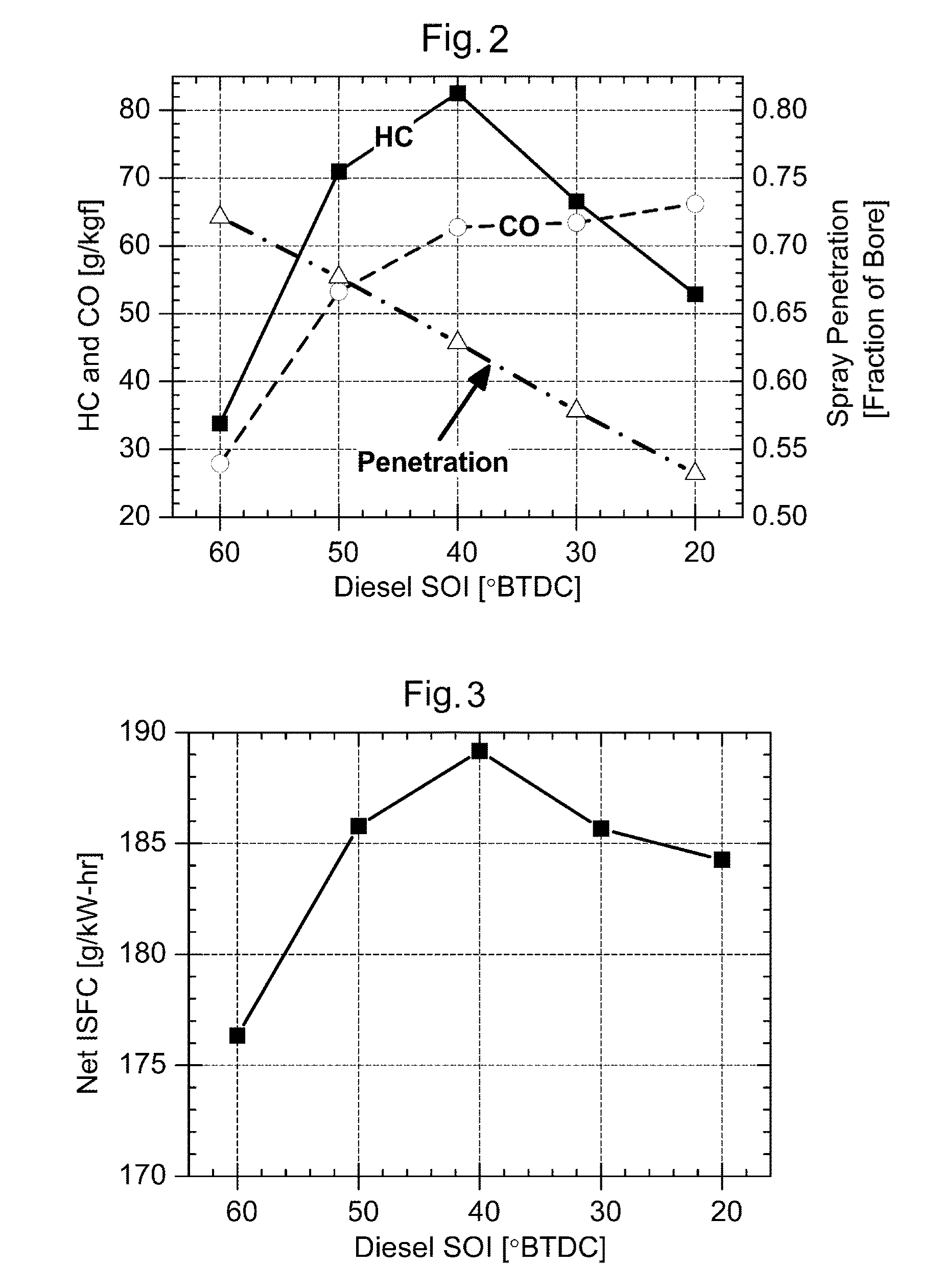
[0020]An experimental version of the invention operating with diesel and gasoline fuels has resulted in what is believed to be the most fuel-efficient internal combustion engine currently known that is also capable of meeting governmental soot emissions limits, NOx emissions limits, and fuel consumption limits for the year 2010 without the need for exhaust gas after-treatment. As for emissions, the engine can readily attain EPA (U.S. Environmental Protection Agency) standards (as defined on Jan. 1, 2010 at Part 1065 of Title 40 of the United States Code of Federal Regulations), including the EPA's emission standards for the heavy duty transient Federal Test Procedure (FTP) (e.g., NOx emissions of less than 1.0 g / kW-hr and soot emissions of less than 0.1 g / kW-hr). Further reductions in emissions are possible if measures such as exhaust after-treatment are implemented. Looking to indicated thermal efficiency as a measure of fuel efficiency (indicated thermal efficiency being a measure of the amount of fuel converted to output power by the engine, as opposed to being lost via heat transfer, exhaust, or other variables), the engine has demonstrated a net thermal efficiency of up to 53%, and a gross thermal efficiency of about 56%. (Net thermal efficiency takes account of work output over the entire engine cycle, whereas gross thermal efficiency only takes account of the expansion and compression strokes, with an approximately 3% difference between the two being common.) In contrast, at the time of this document's preparation, the average conventional diesel engine has a thermal efficiency of approximately 42%, and the average gasoline engine has a thermal efficiency of approximately 25-30%. The invention can therefore beneficially allow an effective reduction in fuel consumption of approximately 20%, while meeting United States emission standards (at least for the year 2010) without the need for burdensome and expensive engine modifications and / or after-treatment systems for soot and / or NOx reduction. It is of interest to note that while the invention operates using compression ignition (i.e., diesel operating principles), the exceptional efficiency was attained using more gasoline than diesel fuel: gasoline accounted for approximately 75%-90% of the total mass of the fuel provided to the engine (at high loads), with the percentage of gasoline dropping to approximately 50% at low loads. Thus, a diesel engine attained enhanced performance using primarily non-diesel fuel. It is expected that in general, most common engines implementing the invention will use a greater proportion of low reactivity fuel than high reactivity fuel.

Problems solved by technology

Greater stratification / gradation in reactivity tends to result in a lower combustion rate.

Method used


Image

  • Engine combustion control via fuel reactivity stratification
  • Engine combustion control via fuel reactivity stratification
  • Engine combustion control via fuel reactivity stratification

Examples


Embodiment Construction

[0027]Before reviewing the invention further, it is initially useful to discuss the concept of “reactivity” in greater detail. In the context of this document, the term “reactivity” generally corresponds to the cetane number of a substance, and / or the converse of the octane number of a substance. The cetane number measures the speed at which a fuel (or other substance) starts to auto-ignite (spontaneously burn) under diesel operation conditions, i.e., under high pressures and temperatures. In a diesel engine, a fuel with higher reactivity (i.e., higher cetane number) will ignite more quickly than a fuel with lower reactivity. In contrast, the octane number—a measurement usually used for gasoline engine fuels rather than diesel fuels—is a measurement of a substance's resistance to autoignition. In general, diesel fuels have high reactivity (high cetane number / low octane number), and gasolines have low reactivity (low cetane number / high octane number).

[0028]As discussed above, the inv...


PUM


Abstract

A compression ignition engine uses two or more fuel charges having two or more reactivities to control the timing and duration of combustion. In a preferred implementation, a lower-reactivity fuel charge is injected or otherwise introduced into the combustion chamber, preferably sufficiently early that it becomes at least substantially homogeneously dispersed within the chamber before a subsequent injection is made. One or more subsequent injections of higher-reactivity fuel charges are then made, and these preferably distribute the higher-reactivity matter within the lower-reactivity chamber space such that combustion begins in the higher-reactivity regions, and with the lower-reactivity regions following thereafter. By appropriately choosing the reactivities of the charges, their relative amounts, and their timing, combustion can be tailored to achieve optimal power output (and thus fuel efficiency), at controlled temperatures (and thus controlled NOx), and with controlled equivalence ratios (and thus controlled soot).

Description

STATEMENT REGARDING FEDERALLY SPONSORED RESEARCH[0001]This invention was made with United States government support awarded by the following agencies:[0002]U.S. Department of Energy (DOE) Grant No.: DE-FC26-06NT42628[0003]U.S. Department of Energy (DOE) Grant No.: DE-AC04-94AL85000The United States government has certain rights in this invention.FIELD OF THE INVENTION[0004]This document concerns an invention relating generally to compression ignition (diesel) engines, and more specifically to combustion optimization methods for diesel engines.BACKGROUND OF THE INVENTION[0005]Diesel (compression ignition) engines are among the most energy-efficient engines available, with admirably high power output per fuel consumption. Unfortunately, they're also among the “dirtiest” engines available, with common diesel engines (at the time of this document's preparation) being prone to high production of nitrogen oxides (commonly denoted NOx), which result in adverse effects such as smog and acid...

Claims


Application Information

Patent Timeline
Patent Type & Authority Patents(United States)
IPC IPC(8): F02B43/00F02M43/00F02M21/02
CPCF02B23/0669F02D19/0692F02D19/0689F02B23/0672Y02T10/36F02D19/081F02D41/3047Y02T10/123Y02T10/125F02B2275/14F02D41/0025F02D19/061F02D41/402F02D19/0649F02B23/06F02B17/005Y02T10/12Y02T10/30F02B1/12
Inventor REITZ, ROLF DENEYSHANSON, REED M.SPLITTER, DEREK A.KOKJOHN, SAGE L.
Owner WISCONSIN ALUMNI RES FOUND
Why Eureka
Try Eureka