Method for producing a control arm, and a control arm

a control arm and control arm technology, applied in the direction of suspensions, suspensions with pivoted suspension arms, and suspensions, can solve the problems of strong vibration of the wheel guiding control arm, unbalance on the vehicle wheel, and robust components with a long service life, so as to increase the bending stiffness, weight and cost saving, without adversely affecting the stiffness

Active Publication Date: 2013-12-31
BENTELER AUTOMOBILTECHNIK GMBH
View PDF15 Cites 16 Cited by
  • Summary
  • Abstract
  • Description
  • Claims
  • Application Information

AI Technical Summary

Benefits of technology

[0014]The light-metal extruded profile with a Pi-shaped cross-section has a structure resembling the capital Greek letter Pi. The profile is also open towards all sides and has corresponding webs and legs which increase the elastic modulus with respect to bending in the corresponding orientation direction of the webs or legs. Because the profile itself is open on all sides, it can be particularly easy processed, because only small forming forces need to be applied and the profile can be easily deformed.
[0029]According to another advantageous feature of the present invention, the legs and the side webs of a control arm may be formed with a trapezoidal taper at least in one end section. In this way, only a narrow surface must be available at a bearing attachment location for the bearing seat. The control arm according to the invention thus makes optimal use of the available space while simultaneously exhibiting an optimal stiffness characteristic in all bending directions.

Problems solved by technology

The wheel guiding control arms are additionally subjected to strong vibrations resulting from different driving conditions, in particular uneven road surfaces, but also unbalances on a vehicle wheel.
Producing a robust component with a long service life requires numerous process steps as well as extensive anticorrosion post-treatment.
Disadvantageously, the hardened structure of welded assemblies fundamentally changes in the region of the weld seam and in the zone around the weld seam affected by the heat.
A clean welding result is frequently difficult to achieve in particular with components having a complex geometry.
Disadvantageously, welded steel structures are also susceptible to corrosion.
Although the weld seams increase the stiffness when the different components are joined to form a control arm, the weight of the component itself also increases due to the additional welding material.
Complex geometrical shapes are possible by casting, which are not possible with a welded steel structure.
For supporting the cores enclosed in cast components, it may sometimes be necessary to leave the exterior sides open, which may adversely affect the torsional stiffness of such profile components.
Another disadvantage of cast components is a high porosity of the component itself.
This results in a lower strength compared to, for example, components processed by forming.
However, the forging process itself in turn increases the production costs of the component, as well as reduces the degrees of freedom in the production.
However, the extrusion process is difficult to control.

Method used


Image

  • Method for producing a control arm, and a control arm
  • Method for producing a control arm, and a control arm
  • Method for producing a control arm, and a control arm

Examples


Embodiment Construction

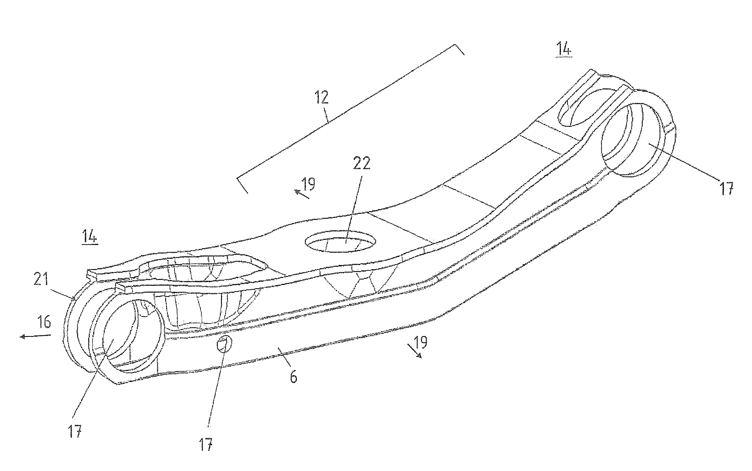
[0041]Throughout all the figures, same or corresponding elements may generally be indicated by same reference numerals. These depicted embodiments are to be understood as illustrative of the invention and not as limiting in any way. It should also be understood that the figures are not necessarily to scale and that the embodiments are sometimes illustrated by graphic symbols, phantom lines, diagrammatic representations and fragmentary views. In certain instances, details which are not necessary for an understanding of the present invention or which render other details difficult to perceive may have been omitted.

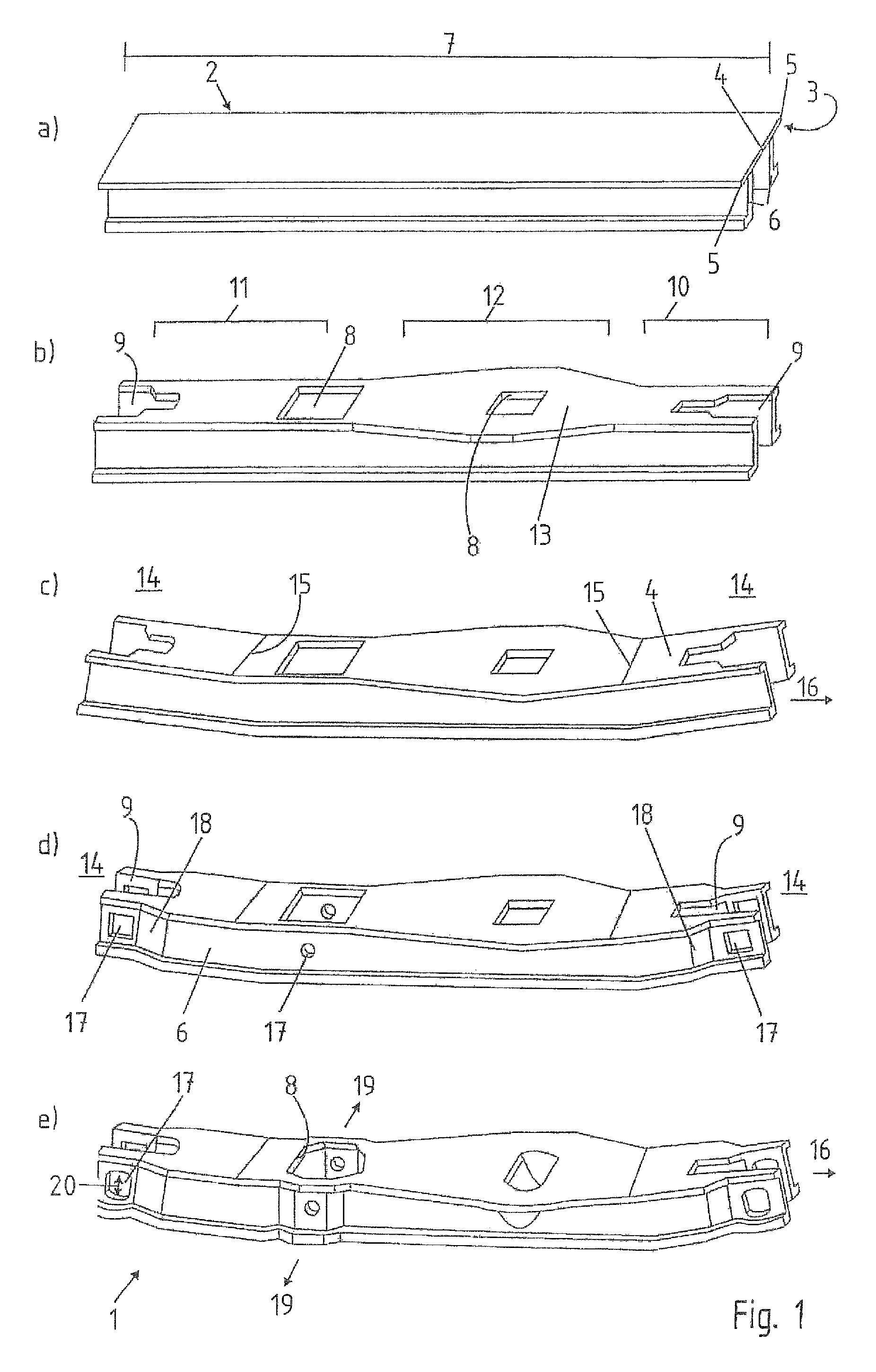
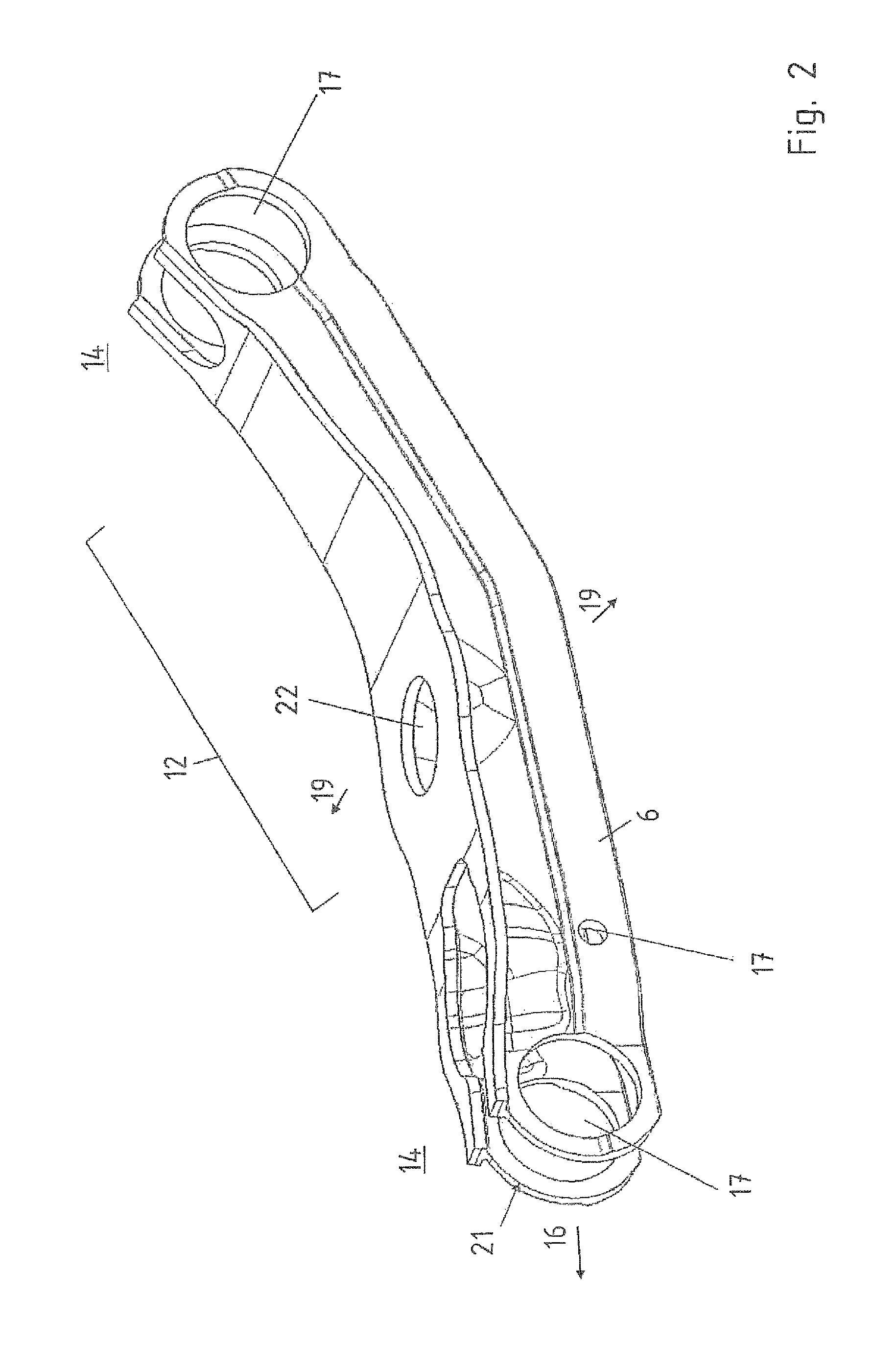
[0042]Turning now to the drawing, and in particular to FIG. 1, there is shown a production method according to the invention for a control arm 1. FIG. 1 is divided into FIGS. 1a) to 1e). FIG. 1a) shows a semi-finished product 2 with a cross-sectional Pi-shaped configuration 3. The semi-finished product 2 has a bottom web 4, side webs 5 extending laterally from the bottom web...


PUM

PropertyMeasurementUnit
longitudinal lengthaaaaaaaaaa
lengthaaaaaaaaaa
distanceaaaaaaaaaa

Abstract

In a method for producing a control arm for arrangement on an automobile axle formed as one-piece part from a light-metal extruded profile, a semi-finished product made from a light-metal extruded profile having a Pi-shaped cross-sectional configuration with a bottom web, side webs extending from the bottom web, and legs projecting from the webs is processed by cutting, whereafter bearing seat openings are introduced and sections of the processed semi-finished product are expanded. A control arm produced with the method of the invention for arrangement on an automobile axle is also disclosed.

Description

CROSS-REFERENCES TO RELATED APPLICATIONS[0001]This application claims the priority of German Patent Application, Serial No. 10 2010 051 741.0, filed Nov. 19, 2010, pursuant to 35 U.S.C. 119(a)-(d), the content of which is incorporated herein by reference in its entirety as if fully set forth herein.BACKGROUND OF THE INVENTION[0002]The present invention relates to a method for producing a control arm for arrangement on an automobile axle and to a control arm for arrangement on an automobile axle.[0003]The following discussion of related art is provided to assist the reader in understanding the advantages of the invention, and is not to be construed as an admission that this related art is prior art to this invention.[0004]Axle components in form of tie rods, control arms or coupling rods are used to transmit static and dynamic wheel forces to an auxiliary axle frame or to an automobile body. These axle components are hereby rotatably and / or pivotally coupled between wheel supports an...

Claims


Application Information

Patent Timeline
Patent Type & Authority Patents(United States)
IPC IPC(8): B60G7/00B60G3/04
CPCB60G7/001B60G2206/16B60G2206/8103B60G2206/8105B60G2206/811B60G2206/83B60G2206/71
Inventor MIELKE, OLIVERPEDERSEN, ROALDKOCH, UWE
Owner BENTELER AUTOMOBILTECHNIK GMBH
Why Eureka
Try Eureka