Turbocharger for an internal combustion engine of a motor vehicle

a technology for internal combustion engines and turbochargers, which is applied to liquid fuel engines, machines/engines, stators, etc., can solve the problems of reducing the efficiency of internal combustion engines, reducing the load and speed range of internal combustion engines in particular, and reducing the size of turbines. to achieve the effect of improving efficiency, improving adaptability of power output, and being flexible and easy to chang

Inactive Publication Date: 2014-01-07
DAIMLER AG
View PDF16 Cites 29 Cited by
  • Summary
  • Abstract
  • Description
  • Claims
  • Application Information

AI Technical Summary

Benefits of technology

[0007]The wrap angles define the areas in degrees in which the spiral passages enclose the locating chamber of the turbine housing. This reduces manufacturing tolerance requirements while improving the efficiency of the internal combustion engine, in particular in the intermediate and lower load and speed ranges. The spiral passage with the smaller wrap angle significantly contributes to an increase in efficiency, in particular in cases of partial admission. In contrast to prior art, the sonic transition of the exhaust gas flow can be generated immediately upstream of the turbine wheel. This reliably prevents the generation of the exhaust gas flow sonic transition in the spiral cross-section of the spiral passage and the occurrence of high flow losses in the downstream outlet region. In addition, the turbocharger according to the invention allows the continued use of low-cost and established sand casting processes, because the production engineering limits of these processes can be observed easily without affecting the efficiency or mechanical stability of the turbocharger housing. In view of the low manufacturing tolerance requirements, alternative low-cost production methods can be used as well.
[0023]The emission values of the internal combustion engine are improved further by providing that an exhaust treatment system, in particular a particulate filter, catalytic converter or SCR system, is provided in the exhaust train downstream of an exhaust gas outlet of the turbine housing. Any back pressure increase of the turbine wheel caused by such an exhaust treatment system can be compensated for advantageously by means of the turbocharger even in the lower or intermediate operating range of the internal combustion engine.

Problems solved by technology

For this reason, the size of the turbine has to be further reduced, thereby reducing its efficiency, in order to meet the power demand of the compressor of the turbocharger.
In the design of turbochargers, which are usually defined on the basis of the nominal operating point, the charge exchange side and the consumption side of the internal combustion engine, the lower load and speed range of internal combustion engines in particular can however not be optimized even when using turbochargers with two asymmetrical spiral passages.
The economical sand casting process commonly used for producing the turbine housing is however subject to limits in terms of production engineering, so that only spiral passages with a width of more than 4.5 mm can be produced reliably.
In addition, casting is often subject to relatively major variances of 10% or more, which leads to further efficiency losses of the turbocharger.

Method used


Image

  • Turbocharger for an internal combustion engine of a motor vehicle
  • Turbocharger for an internal combustion engine of a motor vehicle
  • Turbocharger for an internal combustion engine of a motor vehicle

Examples


Embodiment Construction

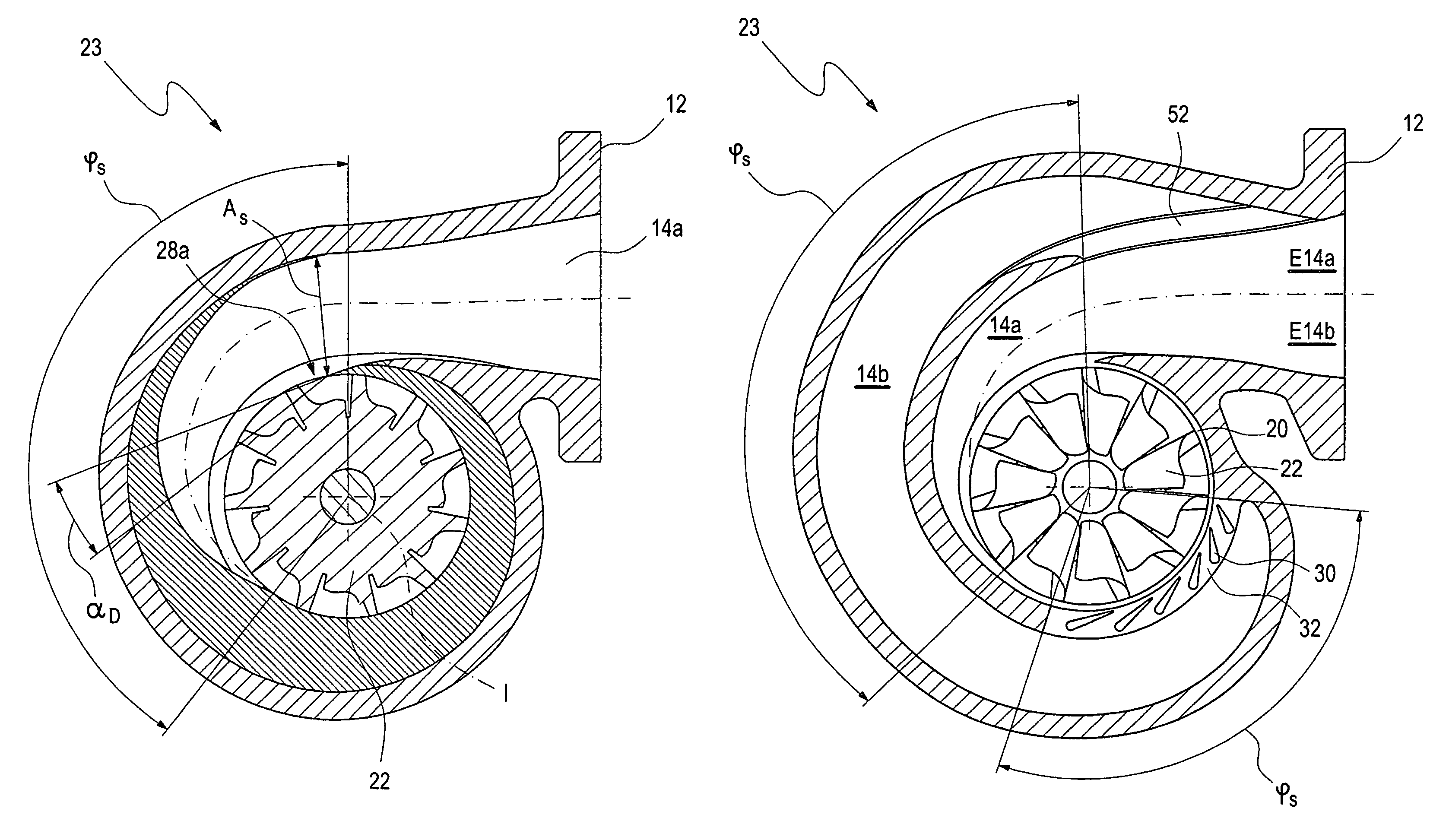
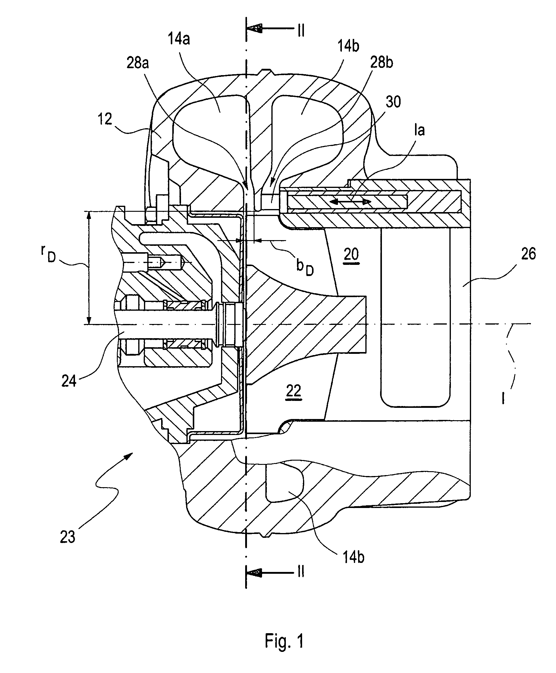
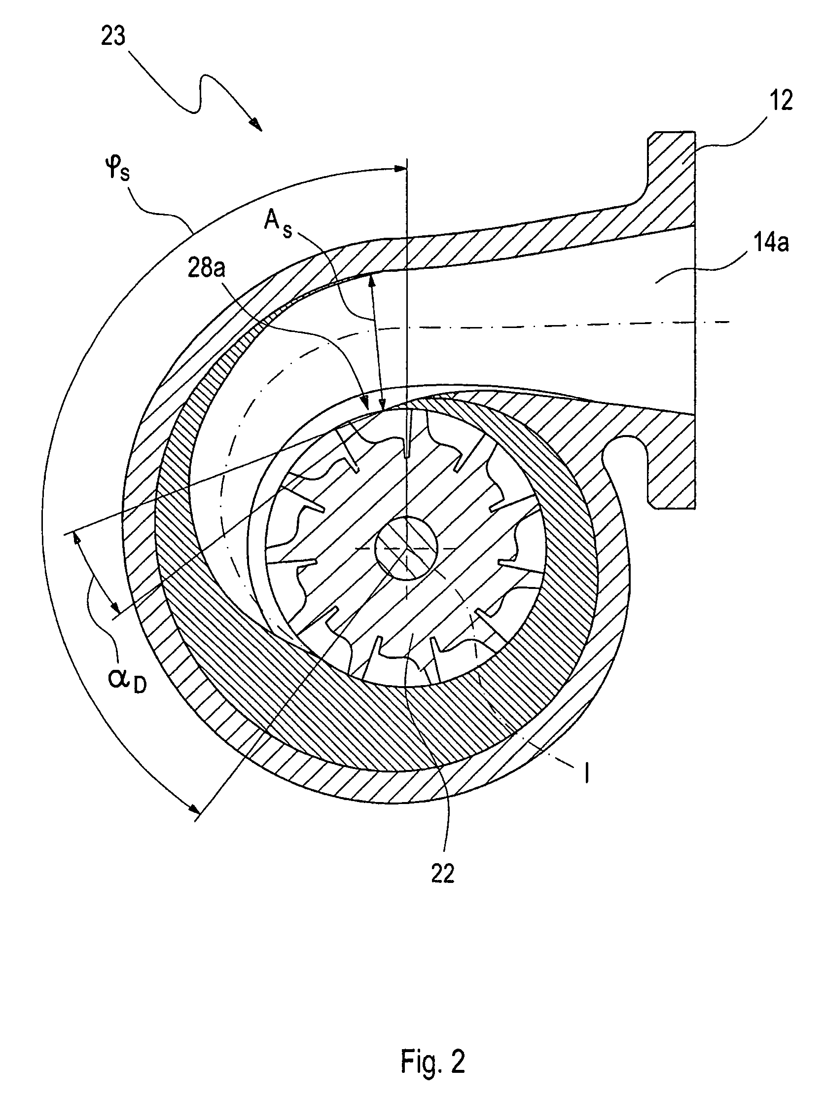
[0035]FIG. 1 is a cross-sectional view of a turbocharger for an internal combustion engine 10 (see FIG. 5) of a motor vehicle according to a first embodiment. The turbocharger comprises a turbine housing 12 with a first and a second spiral passage 14a, 14b, each of which can be coupled to one of several exhaust gas lines 16a, 16b (see FIG. 5) of an exhaust train 18 of the internal combustion engine 10 and through each of which exhaust gas can flow independently. The turbine housing 12 further comprises a turbine wheel 22 in a rotor chamber 20, to which the exhaust gas of the internal combustion engine 10, which can be guided through the two spiral passages 14a, 14b, can be admitted for driving a compressor impeller 25 of a compressor 27 (see FIG. 5) coupled to the turbine wheel 22 for rotation therewith via a drive shaft 24. In order to improve the efficiency of the internal combustion engine 10 in a wider operating range while keeping manufacturing costs as low as possible, the fir...


PUM


Abstract

In a turbocharger for an internal combustion engine of a motor vehicle, comprising a turbine housing having first and second spiral passages, each of which is connected to at least one exhaust gas line of an exhaust train of the internal combustion engine and a turbine wheel disposed within a rotor chamber of the turbine housing and connected to a compressor impeller via a drive shaft for rotation with the impeller, the exhaust gas of the internal combustion engine can be routed through the spiral passages for admission to the turbine wheel via the first and second spiral passages which have different wrap angles around the turbine wheel.

Description

[0001]This is a Continuation-In-Part Application of pending international patent application PCT / EP2009 / 001834 filed Apr. 6, 2009 and claiming the priority of German patent application 10 2008 020 406.4 filed Apr. 24, 2008.BACKGROUND OF THE INVENTION[0002]The invention relates to a turbocharger for an internal combustion engine having a turbine housing with spiral inlet passages coupled to different exhaust gas lines of an exhaust train of the internal combustion engine and to an internal combustion engine, in particular a gasoline and / or diesel engine.[0003]As a result of the continuous tightening of emission limits, such as NOx and particulate emission limits, turbochargers and supercharged engines are subject to increasingly strict requirements as well. Requirements are for example increasingly stringent with respect to boost pressure provision at high exhaust gas recirculation rates over medium to high load demand ranges of the internal combustion engine, whereby, the turbines o...

Claims


Application Information

Patent Timeline
Patent Type & Authority Patents(United States)
IPC IPC(8): F02D23/00
CPCF02B37/22F02B37/025F05D2220/40Y02T10/144F01D9/026F02C6/12Y02T10/12
Inventor KRATSCHRNER, STEPHANSCHMID, WOLFRAMSTILLER, MICHAELSUMSER, SIEGFRIED
Owner DAIMLER AG
Why Eureka
Try Eureka