Eccentric chamfer at inlet of branches in a flow channel

a flow channel and branch channel technology, applied in the direction of continuous combustion chambers, climate sustainability, machines/engines, etc., can solve problems such as generating turbulence, and achieve the effects of reducing flow separation, preventing pressure loss, and increasing jet strength

Active Publication Date: 2014-01-14
SIEMENS ENERGY GLOBAL GMBH & CO KG
View PDF13 Cites 12 Cited by
  • Summary
  • Abstract
  • Description
  • Claims
  • Application Information

AI Technical Summary

Benefits of technology

[0007]It is therefore an objective of the present invention to provide a flow channel with a branch channel having a flow direction substantially perpendicular to the flow direction of a main flow channel which overcomes the mentioned short comings in the state of art. It is a further objective of the present invention to provide an advantageous turbine component.
[0010]Turbulences usually develop at the upstream edges of the inlet opening. The upstream edge of an inlet opening is the edge on the side of the inlet, where the cross flow fluid comes from. The flow sees a very tight corner to flow around, separates from this corner and generates turbulences. In the state of art, turbulences are reduced by providing a chamfer at the inlet opening's edge. However, chamfered downstream edges decrease the effective cross flow through the branch, which is also an undesired result. With the upstream edges of the inlet opening being chamfered or curved and the downstream edges being sharp the unwanted turbulences can still be reduced while at the same time maintaining the effectiveness of the cross flow. This allows an optimised cross flow through the branch. Optimising the cross flow can for example lead to an increased efficiency of impingement cooling due to increased jet strength which results from reduced flow separation and shearing in the hole.
[0016]The advantage of the inventive flow channel and the inventive turbine component lies in the prevention of pressure losses in flow channels by suppression of turbulences, especially for cross flow applications. Moreover, the increased jet strength, which results from reduced flow separation and shearing within the hole, increases the heat transfer coefficient.

Problems solved by technology

The flow sees a very tight corner to flow around, separates from this corner and generates turbulences.
However, chamfered downstream edges decrease the effective cross flow through the branch, which is also an undesired result.

Method used


Image

  • Eccentric chamfer at inlet of branches in a flow channel
  • Eccentric chamfer at inlet of branches in a flow channel
  • Eccentric chamfer at inlet of branches in a flow channel

Examples


first embodiment

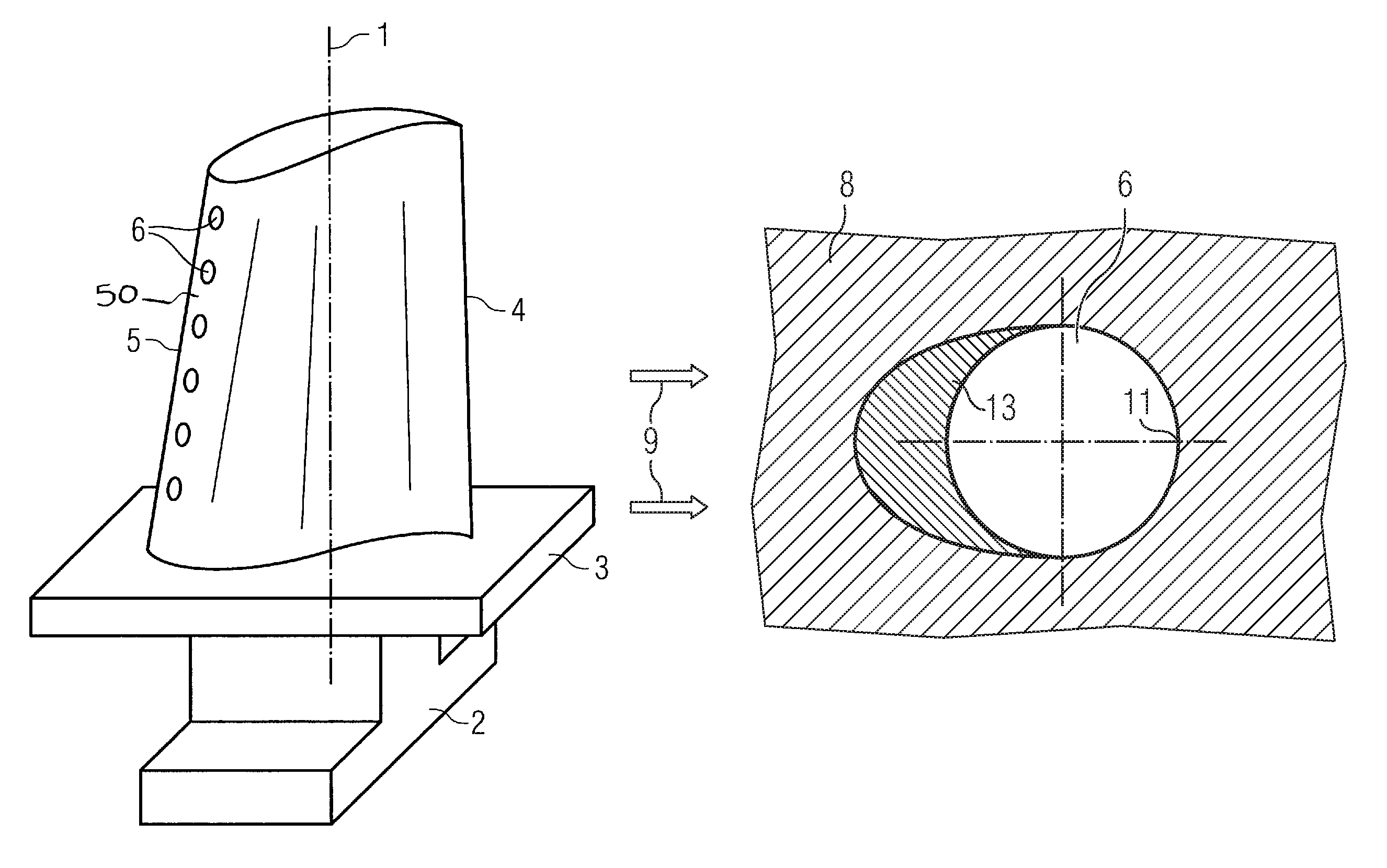
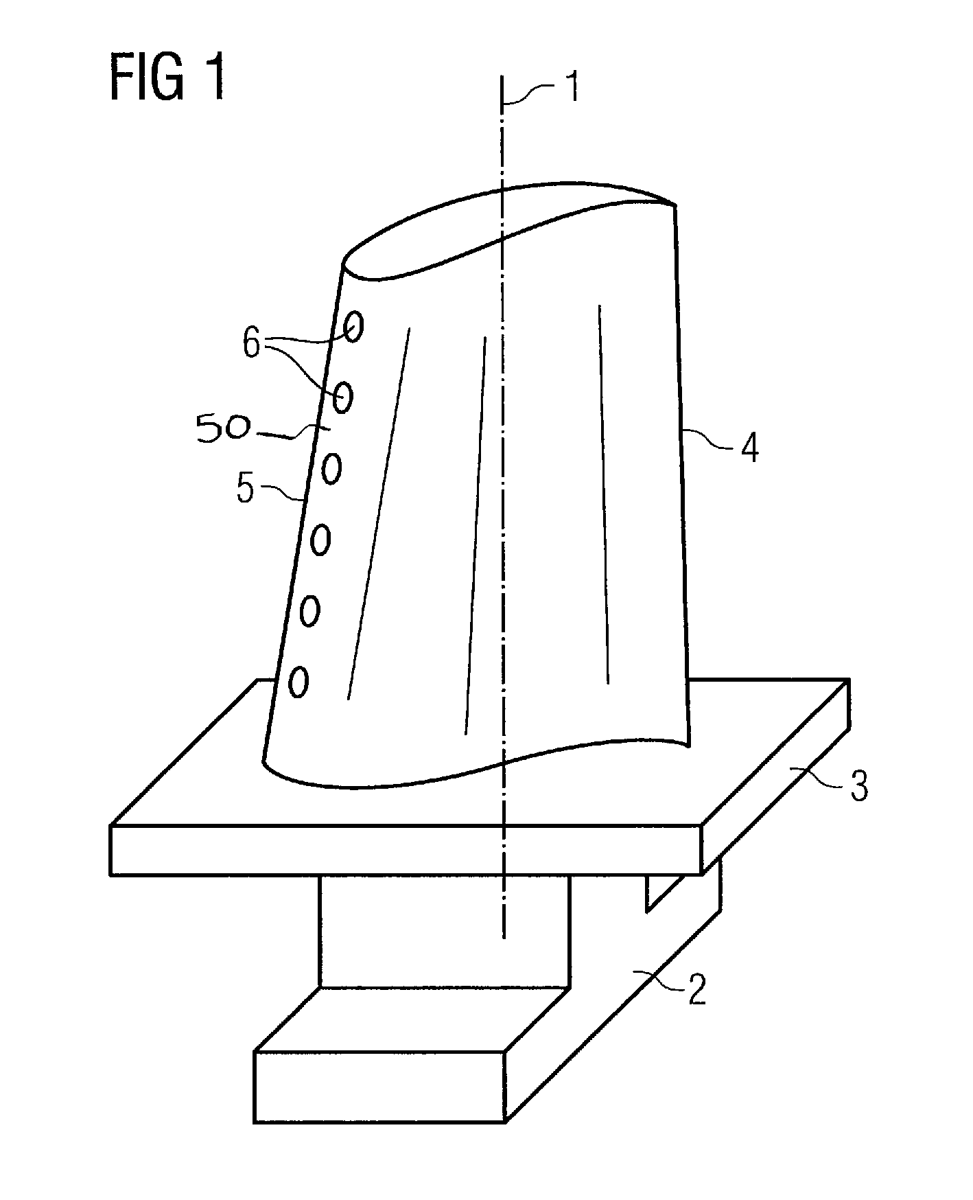
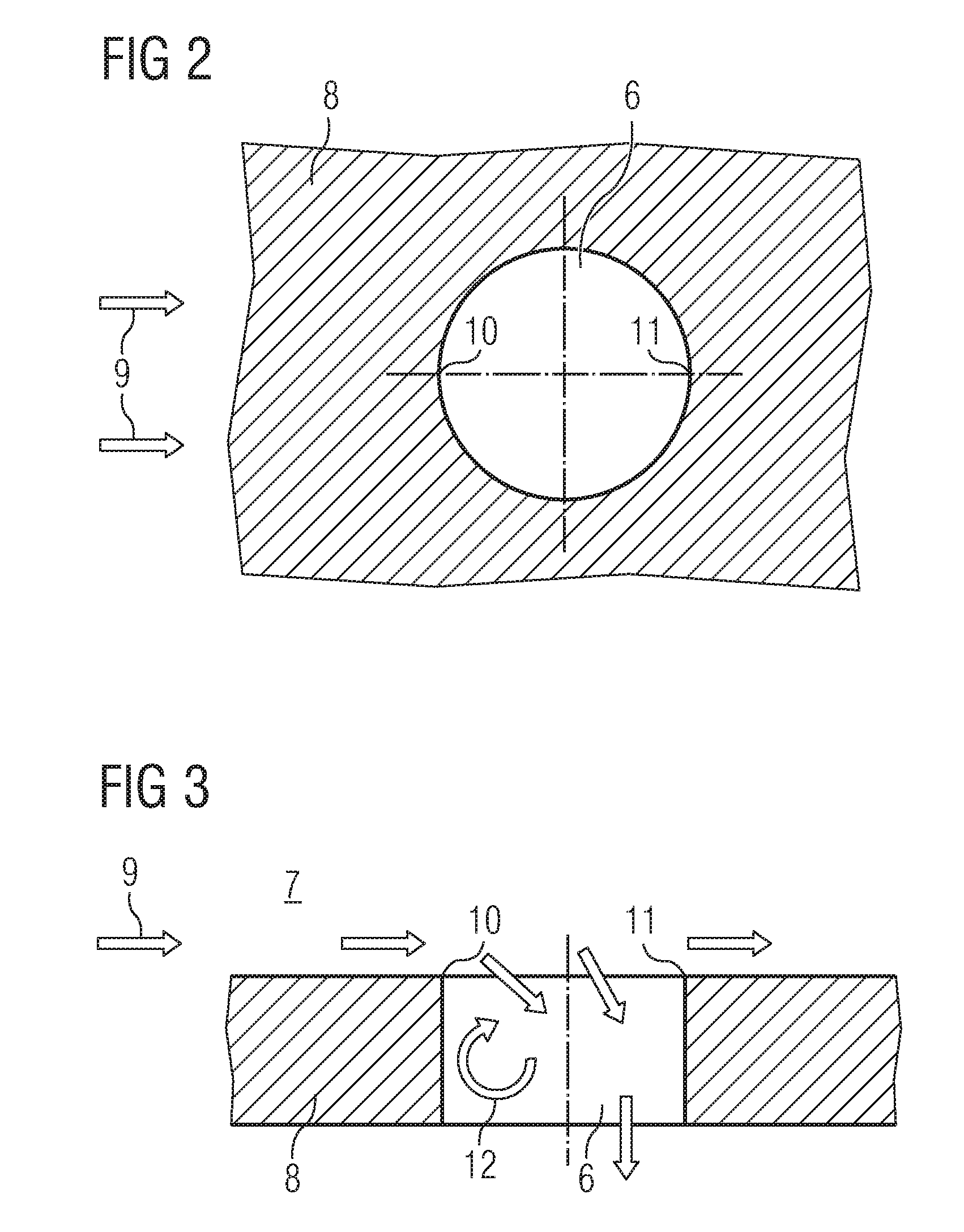
[0029]The turbulences are avoided by the design of the flow channel, in particular the design of the cooling hole's inlet opening, i.e. by the inventive inlet that has an eccentric chamfer at the inlet opening's upstream edge. The eccentric chamfer is machined by reduced Electrical Discharge Machining. FIG. 4 shows, as first embodiment of the invention, a top view of an eccentric chamfered film cooling hole 6 from the inside of the hollow gas turbine rotor blade. FIG. 5 shows the film cooling hole 6 of FIG. 4 in a sectional view along the longitudinal axis of the cooling hole 6. Elements corresponding to elements of FIGS. 2 and 3 will be designated with the same reference numeral and will not be described again. The eccentric chamfer 13 at the upstream edge causes a laminar or a streamline flow without turbulences and unwilling pressure losses. The downstream edge 11 of the inlet is kept sharp to provide an effective use of the cross flow.

[0030]Now a second embodiment of the inventi...

third embodiment

[0034]Also in the holes 6 of the third embodiment the eccentric chamfer 13 increases jet strength, because of a reduced flow separation and shearing within the hole. Therefore the heat transfer coefficient is increased. The top view of the impingement cooling hole of FIG. 8 has the same structure as shown in FIG. 4. The eccentric chamfer 13 can be manufactured by Electrical Discharge Machining, Electro Chemical Machining, or casting.

[0035]The impingement cooling hole can be applied for nozzle guide vane cooling or rotor blade cooling, for example in an aerofoil or in an end wall. Further, it can be applied to gas turbine wall cooling in a combustor transition duct or interduct components. The impingement hole can be manufactured in an impingement tube or impingement plate and fitted to a nozzle guide vane or rotor blade to form an assembly.

[0036]Although different geometric shapes have been described with respect to the film cooling holes and the impingement holes on the one hand an...


PUM


Abstract

A flow channel with a branch channel perpendicular to a main channel including an edge defining an inlet opening of the branch channel is provided. A chamfer is disposed at the upstream edge of the inlet opening and a straight edge is disposed at the downstream edge of the inlet opening, perpendicular to the main channel.

Description

CROSS REFERENCE TO RELATED APPLICATIONS[0001]This application is the US National Stage of International Application No. PCT / EP2008 / 053642, filed Mar. 27, 2008 and claims the benefit thereof. The International Application claims the benefits of European Patent Office application No. 07006444.9 EP filed Mar. 28, 2007, both of the applications are incorporated by reference herein in their entirety.FIELD OF INVENTION[0002]The present invention relates to a flow channel with a branch channel for effective use of cross flow under suppression of turbulences.BACKGROUND OF INVENTION[0003]Fluids like liquids or gases have to be transported via flow channels in numerous technical applications. Flow channels often contain branches, which have a flow direction substantially perpendicular to the flow direction of a main flow channel, for a flow separation where cross flows are used. At such branch turbulences usually develop at the edges of the inlet and cause unwanted pressure losses. One method...

Claims


Application Information

Patent Timeline
Patent Type & Authority Patents(United States)
IPC IPC(8): F03B11/00
CPCY02T50/676F01D5/186F23R2900/03042F23R3/002F05D2260/201F05D2260/607F05D2250/29F05D2250/232F23R2900/03044F05D2260/202F01D5/188F05D2260/221Y02T50/60
Inventor MALTSON, JOHN, DAVID
Owner SIEMENS ENERGY GLOBAL GMBH & CO KG
Why Eureka
Try Eureka