Method of manufacturing high frequency receiving and/or transmitting devices from low temperature co-fired ceramic materials and devices made therefrom

a technology of low temperature cofired ceramics and high frequency receiving and/or transmitting devices, which is applied in the structural form of radiating elements, waveguide devices, resonance antennas, etc., can solve the problems of not being suitable as low k materials for electronic packaging signal processing applications, and not being suitable for low k thin film materials to allow for use as low k portions, etc., to achieve cost-effective

Active Publication Date: 2014-01-21
DU PONT CHINA LTD
View PDF14 Cites 15 Cited by
  • Summary
  • Abstract
  • Description
  • Claims
  • Application Information

AI Technical Summary

Benefits of technology

[0048]Because the invention provides a structure which is fully ceramic, all the advantages of ceramic materials described above in Table 1.1. Specifically, (i) high mechanical strength and rigidity, (ii) hermeticity, (iii) extremely low water absorption, (iv) excellent CTE (Coefficient of Thermal Expansion) match to (IC) chips, (v) smaller levels of cross talk due to higher dielectric constant, and (vi) very compact circuit designs are all provided by the single substrate LTCC of the present invention.

Problems solved by technology

The Donohue et al. dielectric tape composition achieves a dielectric constant in the range of 7-8 and is not suitable as a low k material for electronic packaging signal processing applications.
This dielectric tape composition achieves a dielectric constant in the range of 7-8 and is not suitable as a low k material for electronic packaging signal processing applications.
Previously available LTCC thick film materials have not achieved a sufficiently low k to allow for use as the low k portion of an electronic package for signal processing applications.
Finally, (vi) the higher dielectric constant k of LTCC materials results in very compact circuit designs.
However, the high dielectric constant k of LTCC materials makes it difficult to fabricate antennas and other radiating elements, especially at higher frequencies.
Another drawback of LTCC materials is that their higher dielectric constants k reduce signal transmission speeds.
Gurkovich et al. discloses the use of passive component portions in conjunction with signal processing and does not disclose the ability for passive component portions and signal processing as stand-alone features.
However, their production methods are unwieldy and complex and the individual low k and high k components are expensive, both of which give rise to a high cost per unit manufactured.
This mayalso have a cost impact since costly photo-imaging patterning processes need to be used.Transmission losses can be higher for high Kmaterials due to two reasons.

Method used


Image

  • Method of manufacturing high frequency receiving and/or transmitting devices from low temperature co-fired ceramic materials and devices made therefrom
  • Method of manufacturing high frequency receiving and/or transmitting devices from low temperature co-fired ceramic materials and devices made therefrom
  • Method of manufacturing high frequency receiving and/or transmitting devices from low temperature co-fired ceramic materials and devices made therefrom

Examples


Embodiment Construction

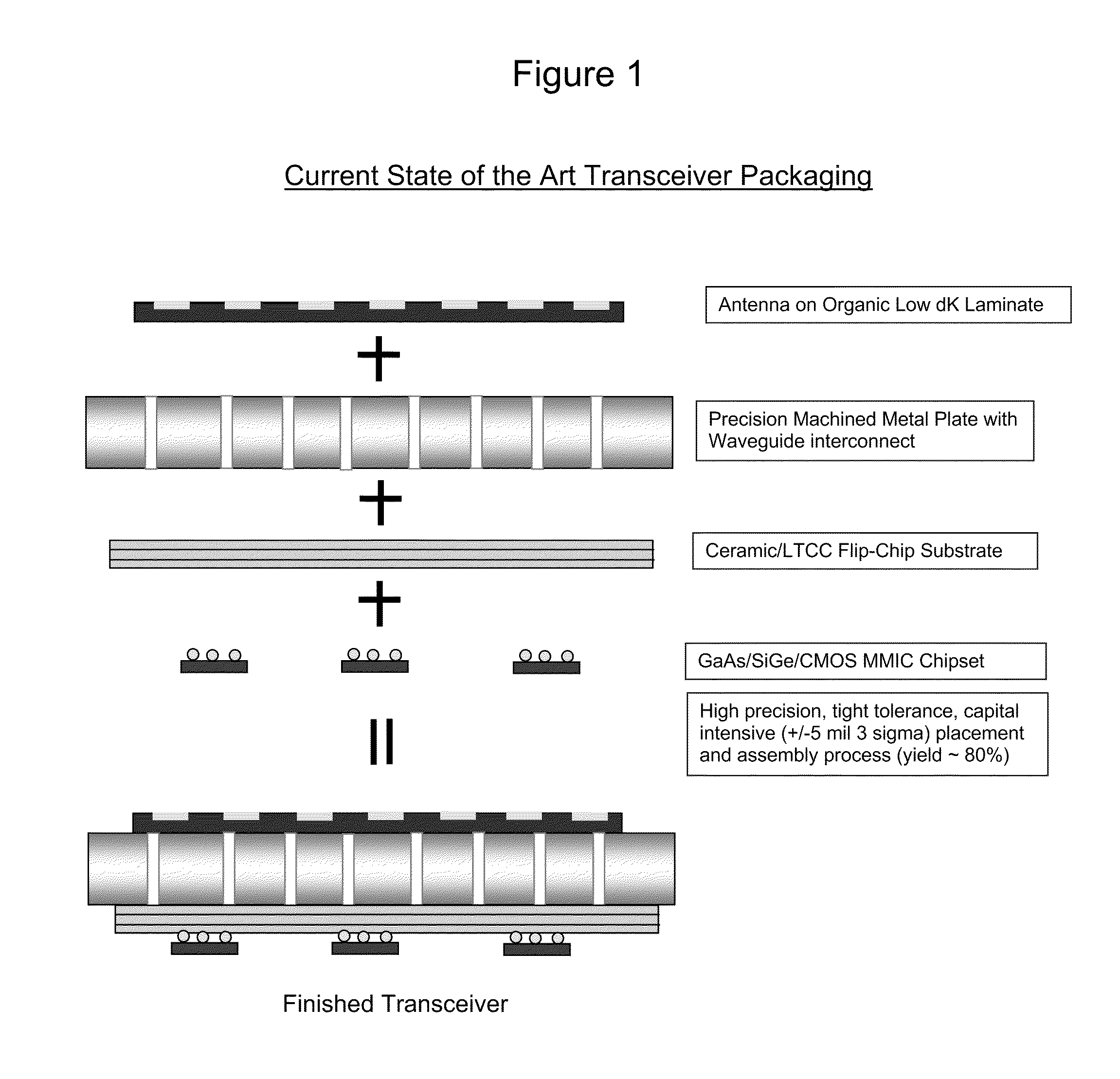
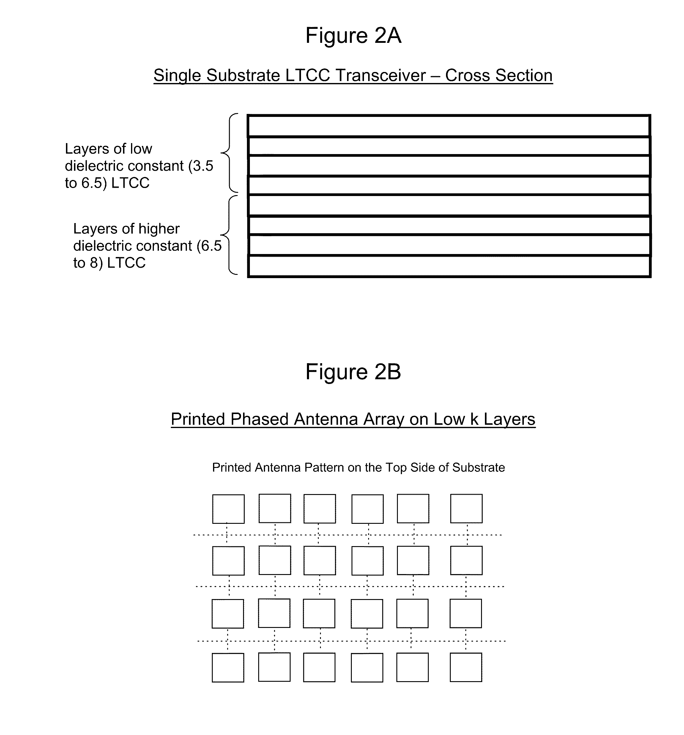
[0036]As a basis for describing the considerable improvement of the methods and the resultant structures and devices that are achieved by the practice of the various embodiments of the invention, the state of the art is described wherein multilayer laminate structures that have both low k and high k layers are used that combine the advantages of both classes of laminate materials while limiting any adverse impact on circuit performance. However, as will be discussed in greater detail, their production methods are unwieldy and complex and the individual low k and high k components are expensive, both of which give rise to a high cost per unit manufactured.

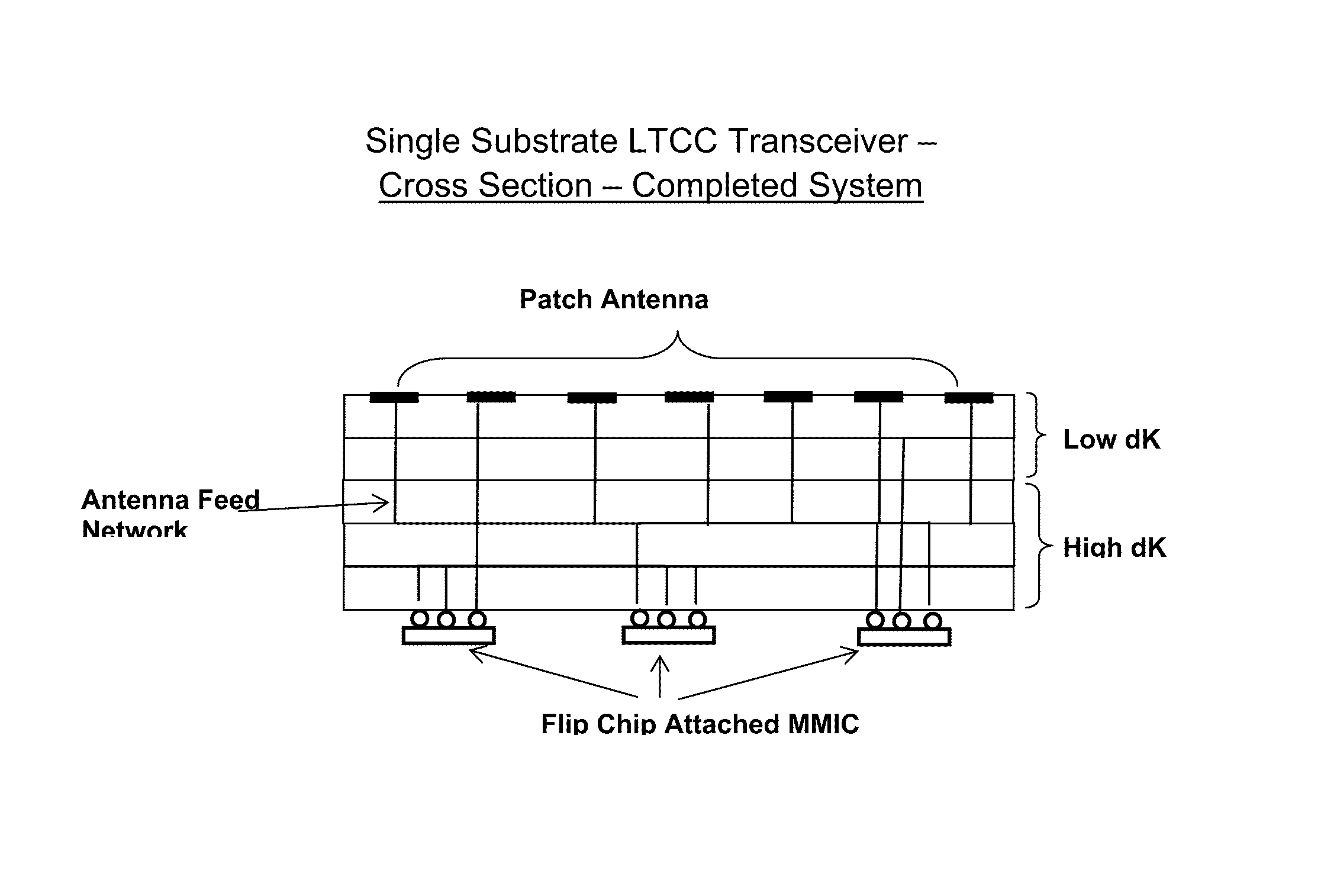
[0037]Because a typical transceiver needs to combine both low k and high k materials for efficient functioning, current designs use a high k ceramic material for chip attachment side of the transceiver and a low k organic material for the antenna side.

[0038]This composite structure between two entirely different types of materials (...


PUM

PropertyMeasurementUnit
dielectric constantaaaaaaaaaa
weight percentaaaaaaaaaa
dielectric constantaaaaaaaaaa

Abstract

The invention relates to methods of forming high frequency receivers, transmitters and transceivers from Low Temperature Co-fired Ceramic (LTCC) materials. Two or more layers of a low k thick film dielectric tape and in contact with each other and two or more layers of a low k thick film dielectric tape and in contact with each other form a low k high k LTCC structure with improved properties and the ability to support economical mass production techniques for high frequency transceivers. The invention also relates to the LTCC receiving, transmitting and transceiving structures and the devices made from such structures.

Description

FIELD OF THE INVENTION[0001]The invention relates to methods of forming high frequency receivers, transmitters and transceivers from Low Temperature Co-fired Ceramic (LTCC) materials. The invention also relates to the LTCC receiving, transmitting and transceiving structures and the devices made from such structures.TECHNICAL BACKGROUND OF THE INVENTION[0002]Recent discoveries of (a) glasses for use in LTCC thick film materials which LTCC thick film materials achieve a sufficiently low dielectric constant (k) to allow for use as the low k portion of an electronic package for signal processing applications, and (b) such LTCC thick film materials which achieve a sufficiently low k to allow for use as the low k portion of an electronic package for signal processing applications, have created the possibility for additional discoveries utilizing such LTCC thick film materials. Such glasses are disclosed and claimed in commonly-assigned, allowed U.S. patent application Ser. No. 11 / 543,742,...

Claims


Application Information

Patent Timeline
Patent Type & Authority Patents(United States)
IPC IPC(8): H01Q1/38
CPCC03C3/19H01L23/66H01L2223/6627H01L2924/3011H01L2223/6677H01L25/0655H05K1/0306H01Q21/065H01L2924/09701C03C3/068H01L25/16H01L2224/16225H01L2924/19032H05K3/4688Y10T29/49016
Inventor NAIR, DEEPUKUMAR M.NAIR, KUMARAN MANIKANTANMCCOMBS, MARK FREDERICKMALERBI, JOAO CARLOSPARISI, JAMES M.
Owner DU PONT CHINA LTD
Why Eureka
Try Eureka