Complex pierced micromechanical part

a micro-mechanical part and complex technology, applied in the field of complex micro-mechanical parts, can solve the problems of high cost and inconvenient tribologically, and achieve the effects of favourable scrap rate and production cost, improved roughness and improved tribological properties

Active Publication Date: 2014-01-28
NIVAROX FAR
View PDF6 Cites 2 Cited by
  • Summary
  • Abstract
  • Description
  • Claims
  • Application Information

AI Technical Summary

Benefits of technology

[0004]It is an object of this invention to overcome all or part of the aforecited drawbacks by proposing a method of fabricating a micromechanical part having a complex geometry with pierced holes, which uses a minimum quantity of material and steps and can provide parts with greatly improved roughness and a very favourable scrap rate and production cost.
[0012]It is thus clear that the method allows the fabrication of a single piece micromechanical part, i.e. with no discontinuity of material, which has a “skin” of material, i.e. a small amount of material, the external surface of which takes up the very favourable roughness of the substrate. This very considerably decreases the cost of the material required on the external layer and improves the overall roughness, especially on the external surface, and improves the tribology thereof. Moreover, the material is selectively deposited by depositing only the quantity of material necessary for the final coating, with no requirement for any subsequent alteration steps.

Problems solved by technology

Fabrication of a micromechanical part purely from synthetic diamond or DLC (diamond like carbon) is very expensive and is not tribologically advantageous due to the unfavourable roughness generated by the thick layer deposition process or by a solid etching method.

Method used


Image

  • Complex pierced micromechanical part
  • Complex pierced micromechanical part
  • Complex pierced micromechanical part

Examples


first embodiment

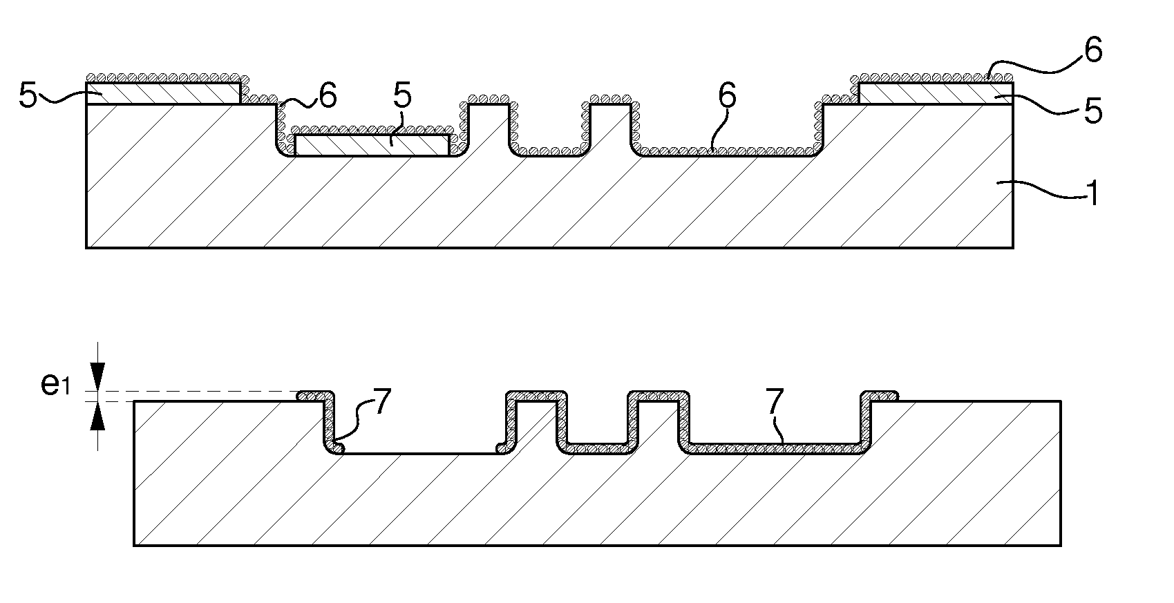
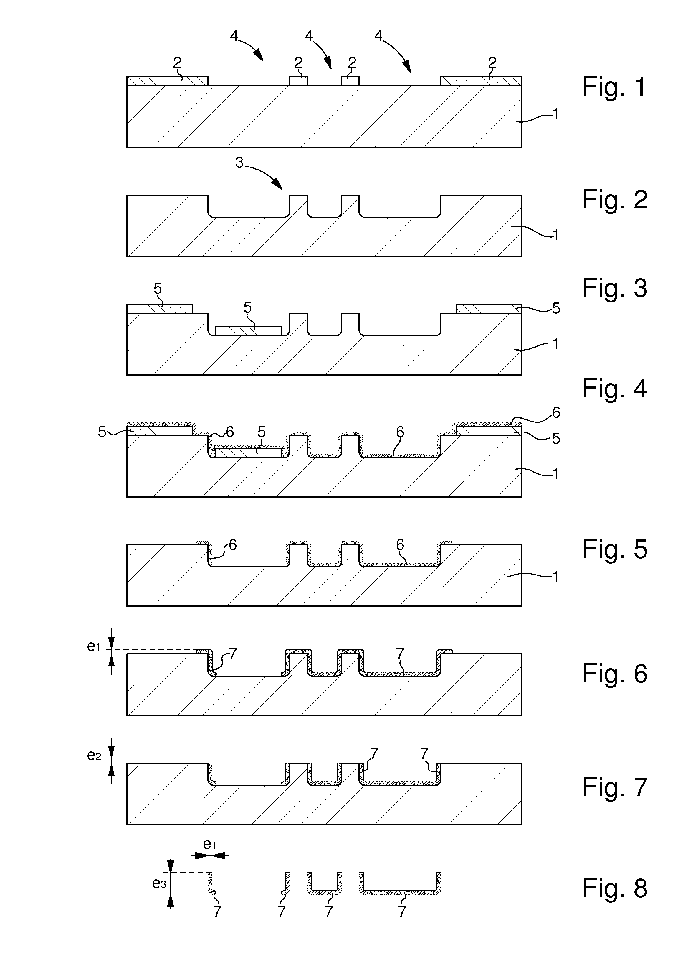
[0034]the method of fabricating this micromechanical part is presented in FIGS. 1 to 8. In step a), the method consists in forming, in a substrate 1, a negative cavity 3 for the future micromechanical part. A large variety of substrates 1 is possible. Preferably, the material of substrate 1 is selected for its low roughness, i.e. the natural feature of having a smooth surface, but also for its resistance to the aggressiveness of the deposition steps.

[0035]By way of example, FIGS. 1 and 2 show step a formed from a silicon substrate 1 for which it is possible to obtain very good roughness, i.e. an arithmetic mean value Ra of substantially less than 10 nm.

[0036]Thus, in a first phase illustrated in FIG. 1, substrate 1 is coated with a mask 2 having holes 4 which leave a top portion of substrate 1 exposed. In a second phase, etching is performed in holes 4. This etching may be wet or dry etching. Finally, in a third phase illustrated in FIG. 2, the mask 2 is removed, leaving only the ne...

second embodiment

[0055]In a fifth step e of the second embodiment, the method consists in depositing a material 27 by chemical vapour phase deposition so that particles 26 are exclusively deposited or remain. At the end of step e), as illustrated in FIG. 13, there is obtained a substrate 21, directly formed with the desired partial layer of material 27.

[0056]The method according to the second embodiment of the invention may also include an optional sixth step g, which is identical to that of the first embodiment, but has not been illustrated.

[0057]In a last step f of the second embodiment, the method consists in removing substrate 21, so as to release the micromechanical part formed in cavity 23, with the same variants and advantages as in the first embodiment.

[0058]At the end of step f, as illustrated in FIG. 14, there is obtained a micromechanical part, formed exclusively by layer 27, the geometry of which at least partially matches cavity 23. Advantageously, when optional step g is not performed,...

third embodiment

[0068]Consequently, in this third embodiment, optional step g) may be used to limit the thickness of said layer 7, 27 in said negative cavity 3, 23, but also to make deposition 8 of the second material flat relative to said limited portion.

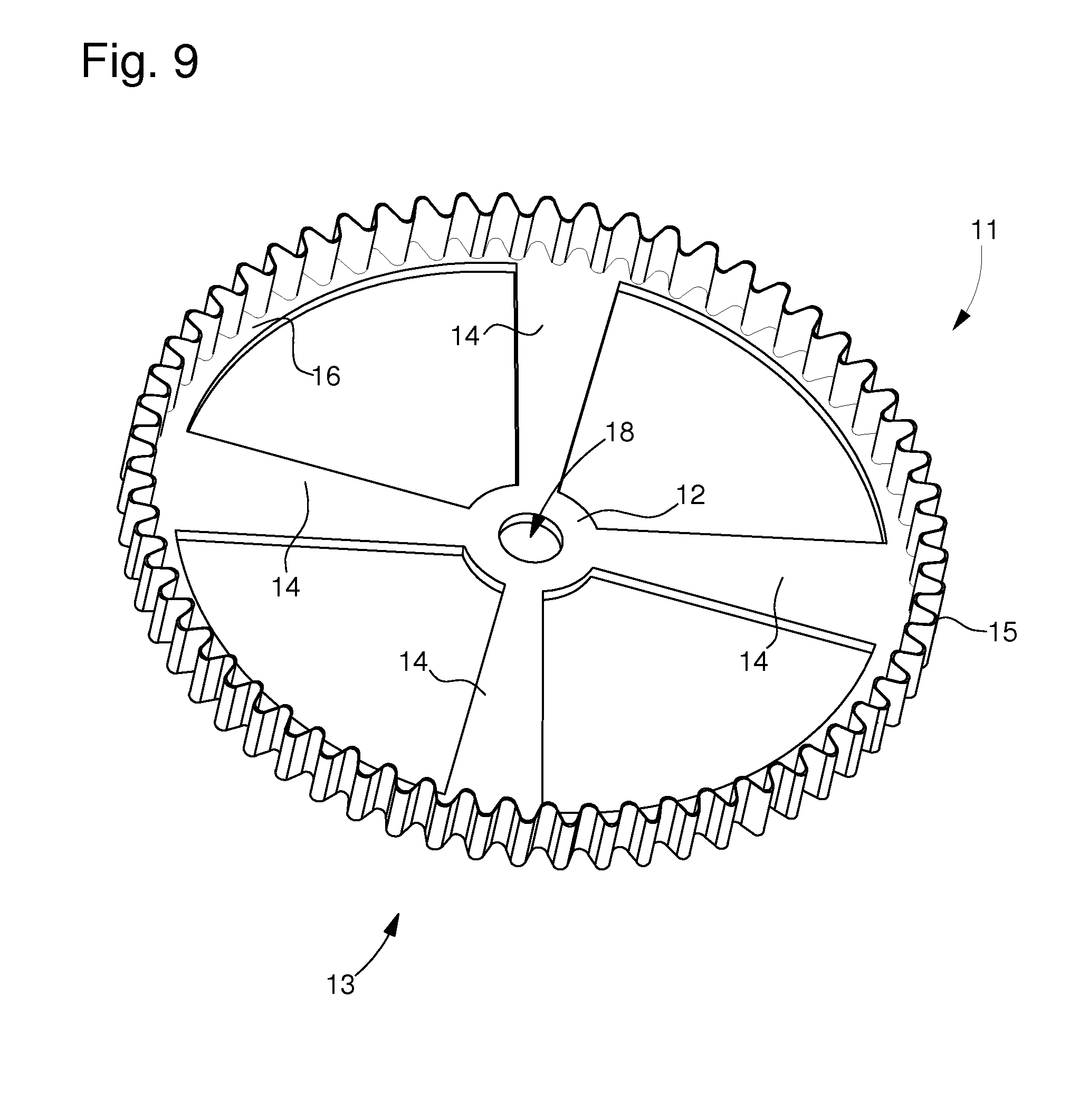
[0069]It is also clear that it is possible to obtain a micromechanical part with the same complexities as in the first two embodiments. By way of non-limiting example, a micromechanical part 31, which can be obtained according to the first embodiment, is shown in FIG. 18. Micromechanical part 31 includes a substantially annular plate 33 from the periphery of which a toothing 35 projects orthogonally, the rest being filled by portion 32 formed by the step h deposition 8, leaving a hole 38 for cooperation, for example, with a pivot pin. The thickness of toothing 35 is thus formed by the thickness e1 of layer 7, 27 deposited in step e of the method and deposition 8 obtained in step h.

[0070]A fourth alternative embodiment to the first and second embod...


PUM

PropertyMeasurementUnit
roughnessaaaaaaaaaa
thickness e1aaaaaaaaaa

Abstract

The invention relates to a method of fabricating a micromechanical part made of a single piece material. According to the invention, the method includes the following steps: a) forming a substrate which includes the negative cavity for said micromechanical part to be fabricated; b) forming a sacrificial layer on one portion of the substrate; c) depositing particles on the substrate intended to form a germ ination layer; d) removing the sacrificial layer so as to selectively leave one portion of the substrate free of any particles; e) depositing a layer of material by chemical vapour phase deposition so that the material is exclusively deposited where the particles remain; f) removing the substrate to release the micromechanical part formed in said negative cavity.

Description

[0001]This application claims priority from European Patent Application No. 11153244.6 filed Feb. 3, 2011, the entire disclosure of which is incorporated herein by reference.FIELD OF THE INVENTION[0002]The invention relates to a complex micromechanical part made from any material, such as, for example, a carbon-based material, and a method of fabricating a part of this kind.BACKGROUND OF THE INVENTION[0003]Fabrication of a micromechanical part purely from synthetic diamond or DLC (diamond like carbon) is very expensive and is not tribologically advantageous due to the unfavourable roughness generated by the thick layer deposition process or by a solid etching method. Consequently, it is currently preferred to coat the micromechanical part using a thin layer of synthetic diamond or DLC, although this does enable obtain all shapes to be obtained, particularly if one portion of the part has to be pierced with a hole.SUMMARY OF THE INVENTION[0004]It is an object of this invention to ove...

Claims


Application Information

Patent Timeline
Patent Type & Authority Patents(United States)
IPC IPC(8): B22C7/00B22D23/00B22D19/00
CPCB81B2201/035B81C99/0085
Inventor CUSIN, PIERRERICHARD, DAVIDDUBOIS, PHILIPPE
Owner NIVAROX FAR
Why Eureka
Try Eureka