Fast charging with negative ramped current profile

a technology of ramped current and negative current, which is applied in the direction of electric vehicles, transportation and packaging, electric power, etc., can solve the problems of increasing the time it takes to fully charge the battery cell, changing the resistance of the various resistance elements, and potentially dangerous failure of lithium-ion batteries. to achieve the effect of reducing the time for fully charging lithium-ion batteries

Active Publication Date: 2014-02-04
TESLA INC
View PDF16 Cites 37 Cited by
  • Summary
  • Abstract
  • Description
  • Claims
  • Application Information

AI Technical Summary

Benefits of technology

[0016]Disclosed is a battery charger and battery charging process for reducing a time for fully charging lithium-ion batteries. The preferred embodiments include a battery cell charging system, including a charger and a controller, for rapidly charging a lithium ion battery cell, the battery cell charging system having a circuit for charging the battery cell using an adjustable voltage charging-profile to apply a charging voltage and a charging current to the battery cell wherein the adjustable voltage charging-profile includes: a first charging stage with a constant first stage charging current and an increasing battery cell voltage with the first stage charging current provided until the first stage charging voltage is about equal to a first stage complete voltage less than a maximum battery cell voltage; an intermediate ramped charging stage, the intermediate ramped charging stage including both an increasing ramped voltage and a decreasing ramped iBat current for the battery cell for the voltage charging range of the first stage complete voltage to about the maximum battery cell voltage; and a final charging stage with a constant final stage charging voltage about equal to the maximum battery cell voltage and a decreasing final stage charging current with the final stage charging voltage provided until the final stage charging current reaches a desired charge complete level.
[0020]In a particular implementation, the battery may be modeled to decrease charging current as battery voltage increases. The model may include an RBad that allows improved charging rates without the negative consequences. The model would represent RBad as a function of the various physical parameters that can negatively affect cycle life. For example, RBad could partially represent the polarization of the negative electrode (Ranode). As Ranode increases, the likelihood of lithium plating on the anode is increased, thereby leading to capacity fade in the battery. So from a modeling perspective, the parameters that affect Ranode, such as temperature, cell age and state of charge can appropriately be adjusted in the charge algorithm to prevent cell damage. There are several examples of these physical, cell level parameters that affect RBad such electrolyte type, electrode design, and anode material. All of these parameters can be experimentally determined and therefore properly modeled to show their effect on a RBad value.
[0021]One source of capacity degradation consequent to fast charging results from side reactions in the negative electrode (i.e., lithium plating). Reducing the charge voltages when charge rates are high minimizes the side reactions and thereby reduces degradation due to fast charging using high charging currents.

Problems solved by technology

However, certain kinds of treatment may cause Li-ion batteries to fail in potentially dangerous ways.
As such, during the last portion of the charging cycle, typically about the last ⅓, the battery cell is charged at a reduced charging current, which means it takes more time to fully charge the battery cell.
Unfortunately, the resistance of the various resistance elements change over time due primarily to various aging factors.

Method used


Image

  • Fast charging with negative ramped current profile
  • Fast charging with negative ramped current profile
  • Fast charging with negative ramped current profile

Examples


Embodiment Construction

[0030]Embodiments of the present invention provide a system and method for a fast battery charger, particularly for lithium-ion battery cells while reducing / eliminating the impact of fast charging on cycle life. The following description is presented to enable one of ordinary skill in the art to make and use the invention and is provided in the context of a patent application and its requirements. Various modifications to the preferred embodiment and the generic principles and features described herein will be readily apparent to those skilled in the art. Thus, the present invention is not intended to be limited to the embodiment shown but is to be accorded the widest scope consistent with the principles and features described herein.

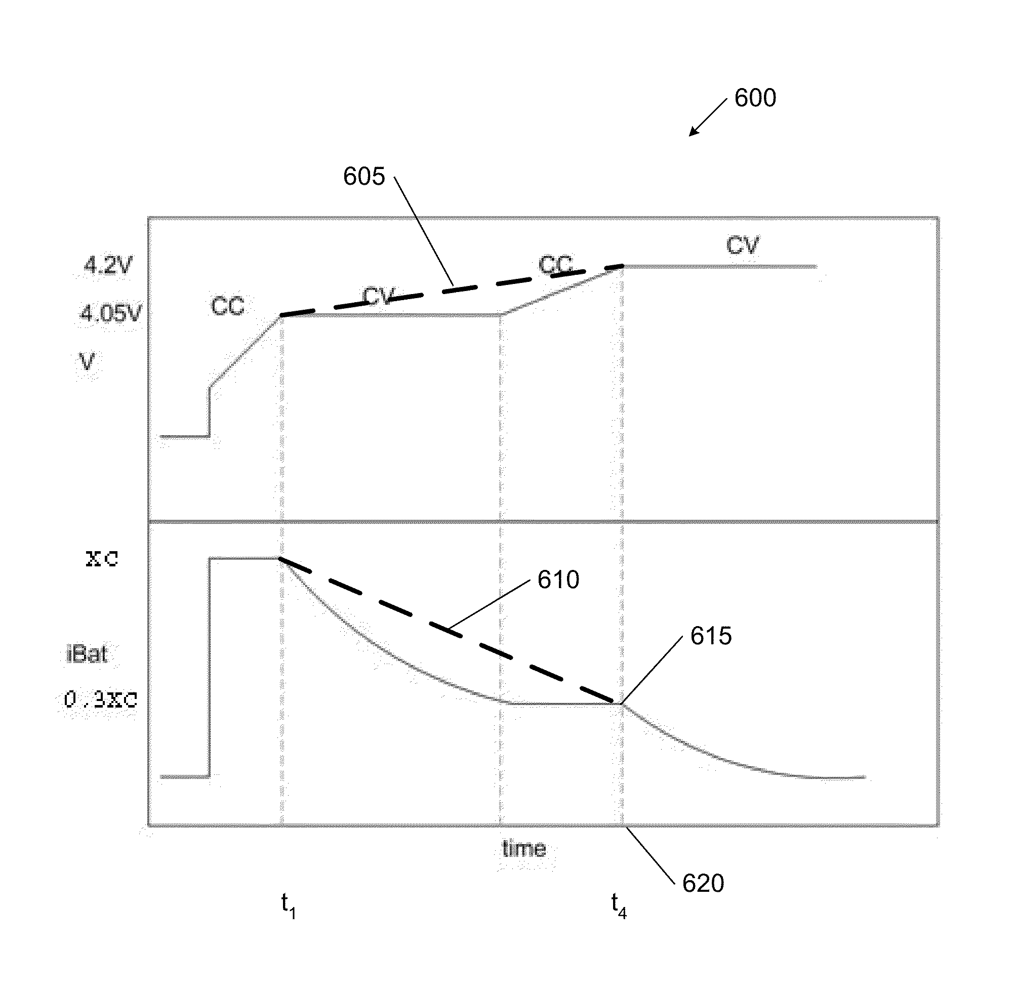
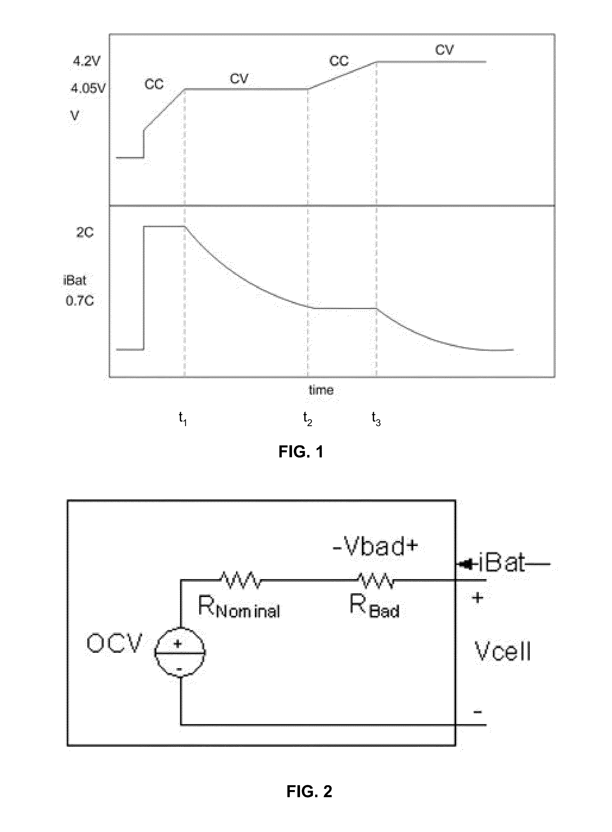
[0031]FIG. 1 is a chart of a simplified multistage fast charge profile for a battery charger. The preferred embodiment for the fast charge profile includes at least four stages: a CC (constant current) first stage, a constant voltage (CV) second stage; ...


PUM


Abstract

A battery cell charging system, including a charger and a controller, for rapidly charging a lithium ion battery cell, the battery cell charging system having a circuit for charging the battery cell using an adjustable voltage charging-profile to apply a charging voltage and a charging current to the battery cell wherein the adjustable voltage charging-profile includes: a first charging stage with a constant first stage charging current and an increasing battery cell voltage with the first stage charging current provided until the first stage charging voltage is about equal to a first stage complete voltage less than a maximum battery cell voltage; an intermediate ramped charging stage, the intermediate ramped charging stage including both an increasing ramped voltage and a decreasing ramped iBat current for the battery cell for the voltage charging range of the first stage complete voltage to about the maximum battery cell voltage; and a final charging stage with a constant final stage charging voltage about equal to the maximum battery cell voltage and a decreasing final stage charging current with the final stage charging voltage provided until the final stage charging current reaches a desired charge complete level.

Description

CROSS REFERENCE TO RELATED APPLICATIONS[0001]This application is related to U.S. application Ser. No. 12 / 505,256 filed 17 Jul. 2009, the contents of which are all expressly incorporated herein for all purposes.BACKGROUND OF THE INVENTION[0002]The present invention relates generally to rechargeable lithium-ion-type chemistry batteries, and more specifically to fast charging of automotive Li-ion battery packs.[0003]Lithium ion batteries are common in consumer electronics. They are one of the most popular types of battery for portable electronics, with one of the best energy-to-weight ratios, no memory effect, and a slow loss of charge when not in use. In addition to uses for consumer electronics, lithium-ion batteries are growing in popularity for defense, automotive, and aerospace applications due to their high energy and power density. However, certain kinds of treatment may cause Li-ion batteries to fail in potentially dangerous ways.[0004]One of the advantages of use of a Li-ion c...

Claims


Application Information

Patent Timeline
Patent Type & Authority Patents(United States)
IPC IPC(8): H02J7/04H02J7/00
CPCH02J7/0073H02J7/0071
Inventor MEHTA, VINEET HARESHSTRAUBEL, JEFFREY BRIAN
Owner TESLA INC
Why Eureka
Try Eureka