Non-etched flat polarization-selective diffractive optical elements

a diffractive optical element and flat polarization technology, applied in the field of non-etched flat polarization selective diffractive optical elements, can solve the problems of not being suitable for many applications, not being cost-effective for many applications, and only being useful in the type of lc hologram

Active Publication Date: 2014-02-04
VIAVI SOLUTIONS INC
View PDF78 Cites 41 Cited by
  • Summary
  • Abstract
  • Description
  • Claims
  • Application Information

AI Technical Summary

Problems solved by technology

Accordingly, these types of LC holograms are typically only useful in optical systems and instrumentation where the light sources are polarized.
Although programmable thin holograms encoded onto LC / SLMs are very versatile, these active components are not cost effective for many applications.
Unfortunately, since the alignment of the liquid crystal is related to an average of different regions it cannot be patterned with precision and thus, is not suitable for many applications.
Unfortunately, the etching and / or molding processes used to form these diffractive optical elements are relatively complex and time consuming.
In addition, the surface relief structure generally requires complex optical thin-film coating processes to protect the delicate structures.

Method used


Image

  • Non-etched flat polarization-selective diffractive optical elements
  • Non-etched flat polarization-selective diffractive optical elements
  • Non-etched flat polarization-selective diffractive optical elements

Examples


Embodiment Construction

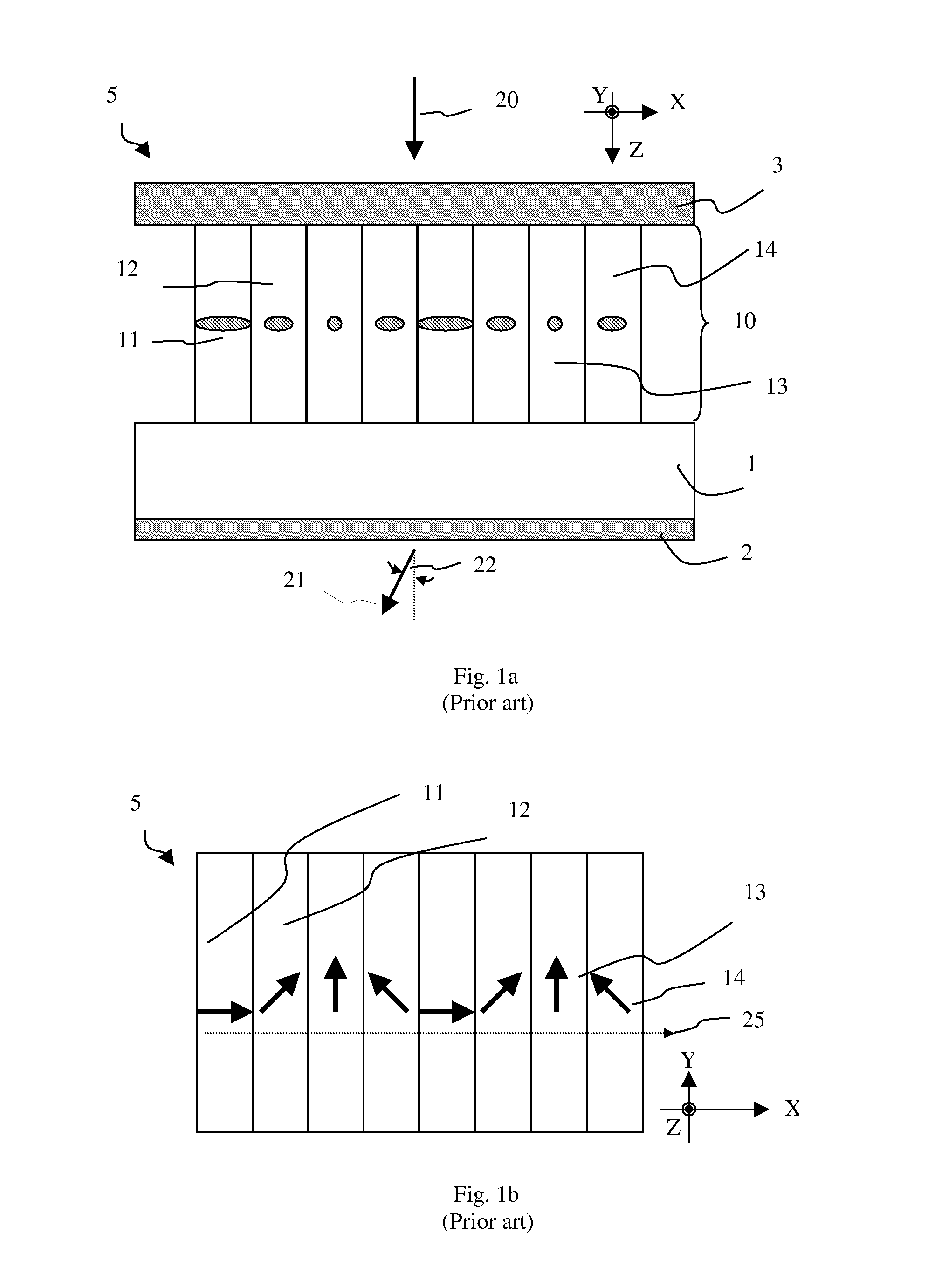
[0073]A prior-art thin liquid crystal (LC) hologram structure is illustrated in FIG. 1, which is a thickness cross-sectional view along the grating vector. The grating vector is the plane where the light is dispersed by diffraction effect. It is also the pixelation direction for a 1D grating or hologram. The hologram 5 includes a substrate 1, onto which an array of pixels 10 having varying azimuthal LC director orientations is disposed. Four discrete azimuthal LC director orientations are shown as 11, 12, 13 and 14. More specifically, the projection of the LC index indicatrix onto the plane of drawing (XZ-plane) is shown. Pixel 11 has its projected director aligned parallel to the X-axis, whereas pixel 13 has its projected director aligned parallel to the Y-axis. The other two states, pixels 12 and 14 have their projected directors contained within the XY plane but non-parallel to both the X- and Y-axes. The hologram element 5 also includes AR coating stacks 2 and 3 to aid transmiss...


PUM

PropertyMeasurementUnit
deflection angleaaaaaaaaaa
out-of-aaaaaaaaaa
out-of-aaaaaaaaaa

Abstract

A method of fabricating an optical element including a liquid crystal layer having a spatially-varying tilt angle includes coating a substrate with a linearly photopolymerizable polymer layer, irradiating the linearly photopolymerizable polymer layer with linearly polarized ultra-violet light at a oblique angle, and coating a layer of liquid crystal material on a surface of the irradiated linearly photopolymerizable polymer layer. The liquid crystal material has a predetermined relationship between its tilt angle and a total dose of the linearly polarized ultra-violet light. The linearly photopolymerizable polymer layer is irradiated with at least one dose of linearly polarized ultra-violet light that is sufficient to induce formation of a plurality of discrete regions within the liquid crystal layer having a larger in-plane birefringence than an adjacent or surrounding region.

Description

CROSS-REFERENCE TO RELATED APPLICATIONS[0001]This application claims the benefit of priority of U.S. Provisional Appl. No. 61 / 232,313 filed Aug. 7, 2009, which is hereby incorporated by reference. In addition, this application is a continuation-in-part of U.S. patent application Ser. No. 12 / 166,988 filed Jul. 2, 2008, now abandoned which claimed priority from U.S. Provisional Appl. No. 60 / 947,690 filed Jul. 3, 2007, both of which are also hereby incorporated by reference.MICROFICHE APPENDIX[0002]Not Applicable.TECHNICAL FIELD[0003]The present application relates generally to liquid crystal (LC) layers having a spatially-varying tilt angle, and in particular, to a method for creating liquid crystal polymer (LCP) having a spatially-varying LCP tilt angle, to optical elements created with the same, and to applications of the LCP.BACKGROUND OF THE INVENTION[0004]Diffraction gratings and more complex thin holograms, encoded onto programmable liquid crystal (LC)-based spatial light modula...

Claims


Application Information

Patent Timeline
Patent Type & Authority Patents(United States)
IPC IPC(8): G02F1/13G02F1/1337
CPCG03H2250/38G11B7/1353G03H2240/11G02B5/1871G02B5/3016G11B2007/0006B29D11/0074G03H2240/23G03H1/22G02F2203/07G02B5/32G11B7/13925G02F1/133753G03H2001/2276G02F1/13342
Inventor TAN, KIM LEONGSHEMO, DAVID M.
Owner VIAVI SOLUTIONS INC
Why Eureka
Try Eureka