Lead with braided reinforcement

a technology of lead and braided reinforcement, which is applied in the direction of spinal electrodes, internal electrodes, therapy, etc., can solve the problems of unintended nerve damage, increased inability to ensure the safety of patients, so as to reduce the risk of fracture during removal, the effect of high tensile strength of the braided structure and high degree of elasticity

Active Publication Date: 2014-02-04
CIRTEC MEDICAL CORP
View PDF34 Cites 12 Cited by
  • Summary
  • Abstract
  • Description
  • Claims
  • Application Information

AI Technical Summary

Benefits of technology

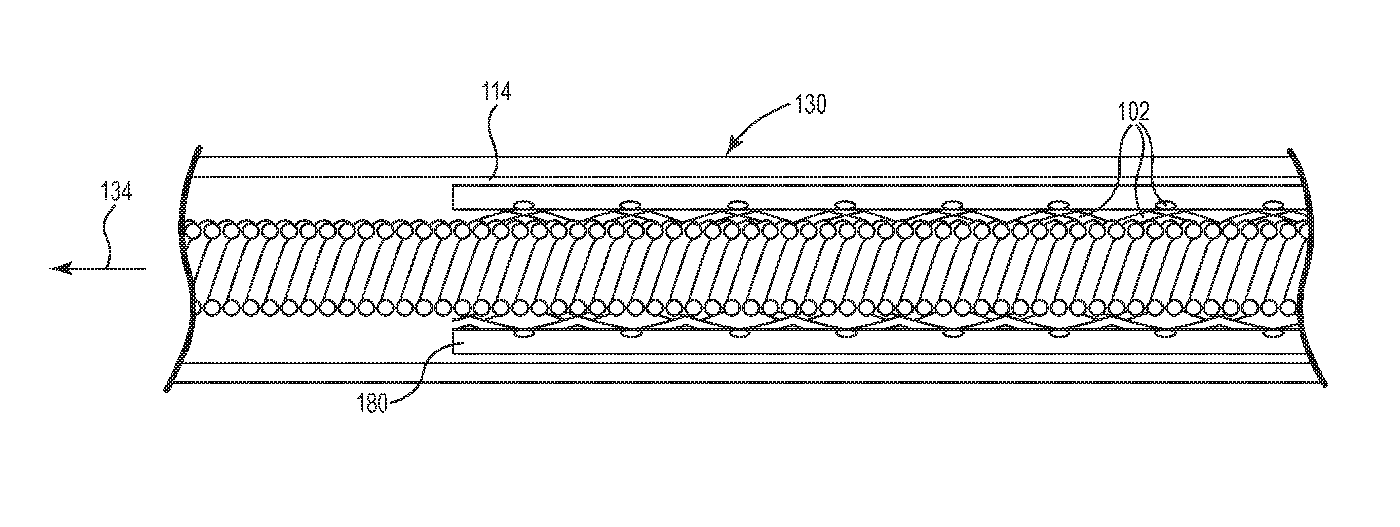
[0010]The present disclosure is directed to a therapy delivery element with a braided reinforcement structure having a free end located near the connector assembly. The present therapy delivery element provides a high degree of elasticity between the connector assembly and the electrode assembly, while the high tensile strength of the braided structure dramatically reduces the risk of fracture during removal. During removal from the patient, the surgeon grasps the free end of the braided structure.
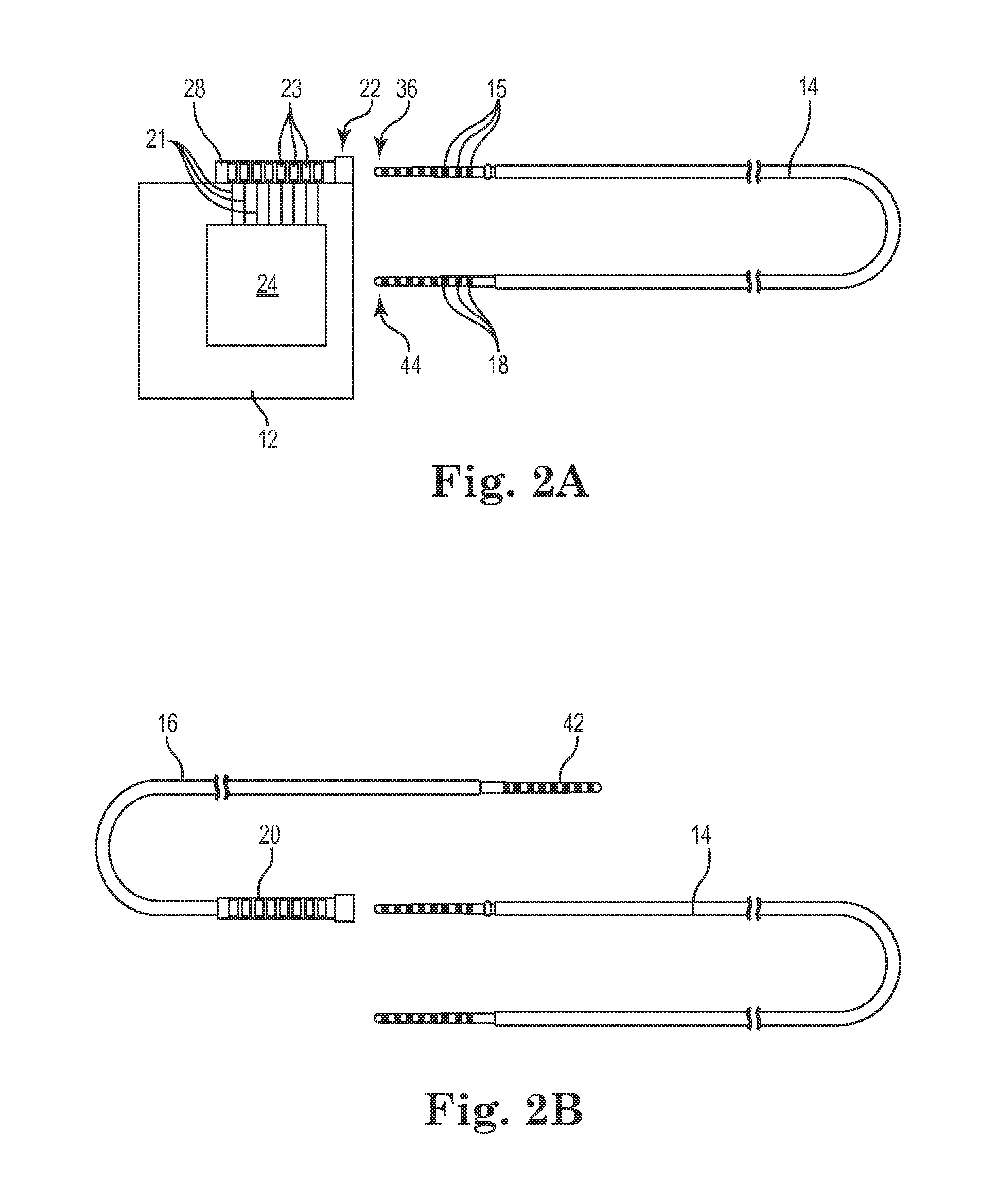
[0011]The present disclosure is directed to a therapy delivery element configured for at least partial insertion in a living body. The therapy delivery element includes a conductor assembly with a plurality of conductors. An electrode assembly is located at a distal end of the conductor assembly. The electrode assembly includes a plurality of electrodes that are electrically coupled to the conductors. A connector assembly is located at a proximal end of the conductor assembly. The connector assembly includes a plurality of electrical contacts that are electrically coupled to the conductors. The braided structure surrounds the conductor assembly. A distal end of the braided structure is attached to an electrode assembly and a free floating proximal end is located near a connector assembly. An outer tubing surrounds the braided structure. The outer tubing includes a proximal end attached to the connector assembly and a distal end attached to the braided structure near the electrode assembly or attached directly to the electrode assembly. A proximal tension force applied to the connector assembly acts substantially on the outer tubing and the conductor assembly, providing substantial axial elasticity. A proximal tension force applied to the free floating proximal end acts substantially on the braided structure to provide high tensile strength during removal.
[0013]A tension force applied to the free floating end of the braided structure provides a percent elongation in a range between about 0.5% to about 15%. The tension force applied to the free floating end of the braided structure provides a yield strength in a range between about 8 lbs. to about 15 lbs. A tension force applied to the connector assembly provides a percent elongation in a range between about 5% to about 30%. The tension force applied to the connector assembly provides a yield strength in a range between about 1 lbs. to about 7 lbs. The yield strength of the present therapy delivery element when the tension force is applied to the free floating proximal end of the braided structure is about 5 times greater than the yield strength when the tension force is applied to the connector assembly. Consequently, the present therapy delivery element combines a high level of strain relief with sufficient tensile strength to permit removal from the patient with minimal risk of fragmentation.

Problems solved by technology

The efficacy of the selected electrode can fade over time due to dislodgement or other causes.
The patient is thereby exposed to the additional dangers associated with extended periods of time under a general anesthetic.
As can be appreciated, unintended movement of any object positioned proximate a nerve may cause unintended nerve damage.
On the other hand, if the target nerve is too close to the electrode, inflammation or injury to the nerve can result, diminishing efficacy and possibly causing patient discomfort.
Tined leads can create problems during removal or explant.
If the anchoring of the tines is stronger than the lead itself, the lead may break during removal, leaving fragments behind.
These fragments can migrate creating pain and increasing the risk of infection.

Method used


Image

  • Lead with braided reinforcement
  • Lead with braided reinforcement
  • Lead with braided reinforcement

Examples


Embodiment Construction

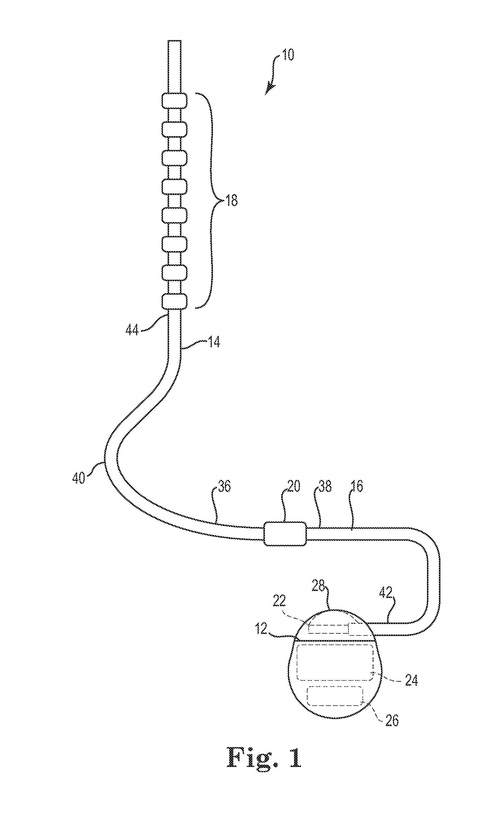
[0038]The description that follows highlights spinal cord stimulation (SCS) system, the treatment of pelvic floor disorders, and peripheral nerve field stimulation (PNFS). However, it is to be understood that the disclosure relates to any type of implantable therapy delivery system with one or more therapy delivery elements with one or more electrodes or sensors. For example, the present disclosure may be used as part of a pacemaker, a defibrillator, a cochlear stimulator, a retinal stimulator, a stimulator configured to produce coordinated limb movement, a cortical stimulator, a deep brain stimulator, microstimulator, or in any other neural stimulator configured to treat sleep apnea, shoulder sublaxation, headache, etc.

[0039]In another embodiment, one or more of the therapy delivery elements may be a fluid or drug delivery conduit, such as a catheter, including an inner lumen that is placed to deliver a fluid, such as pharmaceutical agents, insulin, pain relieving agents, gene ther...


PUM

PropertyMeasurementUnit
elongationaaaaaaaaaa
lengthaaaaaaaaaa

Abstract

A therapy delivery element configured for at least partial insertion in a living body. A braided structure surrounds the conductor assembly. A distal end of the braided structure is attached to an electrode assembly and a free floating proximal end is located near a connector assembly. An outer tubing surrounds the braided structure. The outer tubing includes a proximal end attached to the connector assembly and a distal end attached to the braided structure near the electrode assembly. A proximal tension force applied to the connector assembly acts substantially on the outer tubing and the conductor assembly and a proximal tension force applied to the free floating proximal end acts substantially on the braided structure.

Description

FIELD[0001]The present disclosure is directed to a method and apparatus that allows for stimulation of body tissue, particularly nerves. More specifically, this disclosure relates to an implantable medical electrical lead with a braided reinforcement. The present lead can be used with or without fixation structures to provide stability for the stimulation electrodes. Moreover, this disclosure relates to the method of implantation and anchoring of the medical electrical lead electrodes in operative relation to a selected nerve to allow for stimulation.BACKGROUND[0002]Implantable medical electronics devices consist of an implanted pulse generator that is used to provide electrical stimulation to certain tissues and an implantable lead or leads that are used to transmit the electrical impulse to the targeted tissues. Examples include cardiac pacemaking, and a number of related applications for cardiac rhythm management, treatments for congestive heart failure, and implanted defibrillat...

Claims


Application Information

Patent Timeline
Patent Type & Authority Patents(United States)
IPC IPC(8): A61N1/00
CPCA61N1/00A61N1/05A61N1/0551Y10T29/49208Y10T29/4921
Inventor FINLEY, JAMESSWOYER, JOHN
Owner CIRTEC MEDICAL CORP
Why Eureka
Try Eureka