High temperature, high pressure electrolyser with allothermal functioning and high production capacity

a technology of allothermal functioning and high production capacity, which is applied in the field of high temperature endothermal electrolysis, can solve the problems of increasing the cost of the whole boiler, and not being able to operate under high pressure i.e. several tens of bars of water vapour or food-grade mixtur

Inactive Publication Date: 2014-02-11
COMMISSARIAT A LENERGIE ATOMIQUE ET AUX ENERGIES ALTERNATIVES
View PDF16 Cites 1 Cited by
  • Summary
  • Abstract
  • Description
  • Claims
  • Application Information

AI Technical Summary

Benefits of technology

[0040]The previously stated objectives are attained with an electrolyser consisting of a chamber that is tight at high pressure in which electrolysis supporting plates are alternately arranged with heating plates. On each supporting plate, a mosaic of small-sized electrolysis cells is plated of which at least part is mounted in series, which makes it possible to limit the intensity of the electric current passing through the different cells of the electrolyser, and hence to limit the electric power dissipated in the form of heat.
[0041]The heating plates can provide the electrolyser with the necessary quantity of heat for its functioning, since the heat is no longer provided by Joule effect due to functioning under endothermal mode with reduced irreversibility terms. The use of heating plates integrated in the electrolyser makes it possible to maintain the temperature of all the electrolysis cells with a variation in temperature of less than 30° C. between the inlet and outlet of the electrolyser and with superheating of the hot source of less than 50° C. relative to the operating temperature of the electrolyser.
[0042]According to one preferred embodiment of the present invention, an electrolyser is provided using a high number of small-sized elementary cells mounted in series, which makes it possible to limit the intensity of the electric current passing through the different cells of the electrolyser, and hence to limit the electric power dissipated in the form of heat. With mounting in series it is effectively possible, for electric supply to a supporting plate, only to require intensity that is equal to the intensity necessary for an electrolysis cell of very small size.

Problems solved by technology

These electrolysers are currently at the experimental stage or are demonstration prototypes, and are supplied with water vapour or a vapour / hydrogen mixture at very high temperature, but they cannot operate under high pressure i.e. several tens of bars of water vapour or food-grade mixture.
The design of electrolysers currently being developed, in which the outflow of the water vapour / hydrogen mixture under pressure takes place in a cavity formed by the electrodes in ceramic material surrounded by air at atmospheric pressure, does not at the present time allow this type of electrolyser to operate at high pressure i.e. several tens of bars of gas mixture.
However, simulation thermal calculations of an electrolyser functioning endothermally show:that, to maintain good conditions for endothermal functioning i.e. a temperature higher than the endothermism threshold in the entire electrolyser, it is necessary to have strong superheating and a high flow rate of the water vapour on entering the electrolyser which, having regard to the required temperature (over 1100° C. in this case) will greatly increase the costs of the boiler and of the entire installation,that this solution is not the best indicated to provide stable, homogeneous temperature conditions for electrolyser operation, unless the food-grade water vapour is supplied at high mass flow rates.
This also translates as high flow rates, hence head losses, in the exchanger, electrolyser and piping, which will impact energy costs for compression equipment.
The second solution consists of providing the necessary heat by means of a hot heat-transfer gas mixed with water vapour or water vapour / hydrogen mixture entering the electrolyser, this solution requiring additional equipment to separate the chemical bodies downstream of the electrolyser in order to collect the heat-transfer gas, which causes losses of heat-transfer gas.
It also requires a high mass flow of heat-transfer gas under low pressure, leading to limited performance i.e. gas head losses through the electrolyser and limited electrolyser power.
Document WO2004 / 113590 describes a device to carry out alkaline electrolysis which takes place in liquid phase only, which limits the operating temperature to values below the critical temperature of water which is 374° C. Therefore, it is not possible with this device to operate in a temperature range allowing reversible voltages values to be achieved in endothermal mode.
It is effectively not possible to design piping and compression stages that can avoid too great head losses at such low pressure levels.
Therefore currently known solutions do not allow an efficient reduction in the consumption of energy to be supplied to an electrolyser, since significant overheating is required.
Hence there are no solutions at the present time allowing the production of a substantial quantity of hydrogen at high temperature and pressure and in endothermal mode with low intensity electric currents.

Method used


Image

  • High temperature, high pressure electrolyser with allothermal functioning and high production capacity
  • High temperature, high pressure electrolyser with allothermal functioning and high production capacity
  • High temperature, high pressure electrolyser with allothermal functioning and high production capacity

Examples


first embodiment

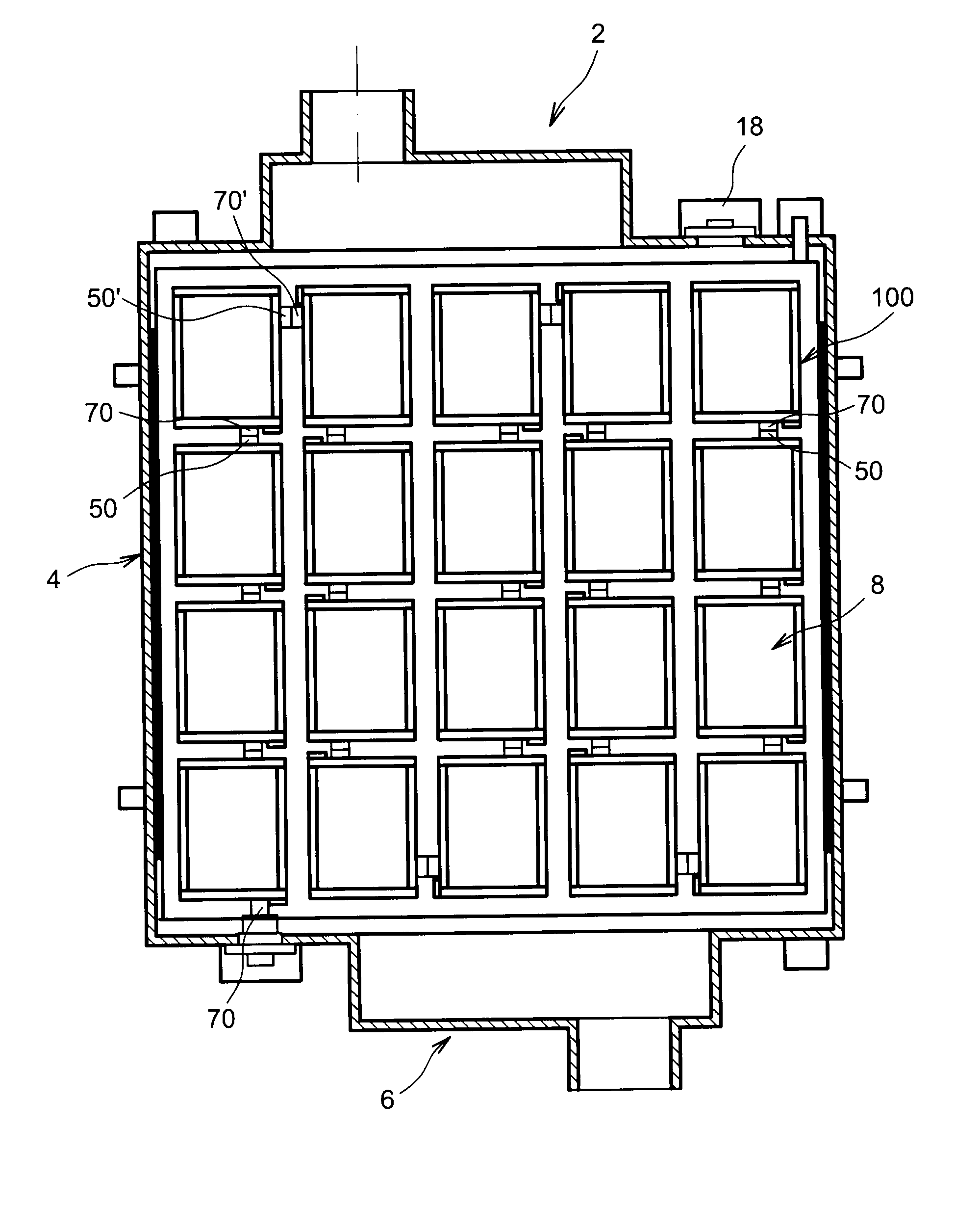
[0072]In one first embodiment, the electrolysis cells are distributed in rows and columns, the cells of one same column being electrically connected in series, the columns being connected in series and the electrolysis plates being connected to each other in series.

second embodiment

[0073]In a second embodiment, the electrolysis cells are distributed in rows and columns, the cells of one same column being electrically connected in series, the columns being connected in series and the electrolysis plates being connected in parallel.

third embodiment

[0074]In a third embodiment, the electrolysis cells are distributed in rows and columns, each column comprising a lower number of cells than the number of cells in series corresponding to the breakdown voltage, said columns all being connected in parallel from one plate to another.

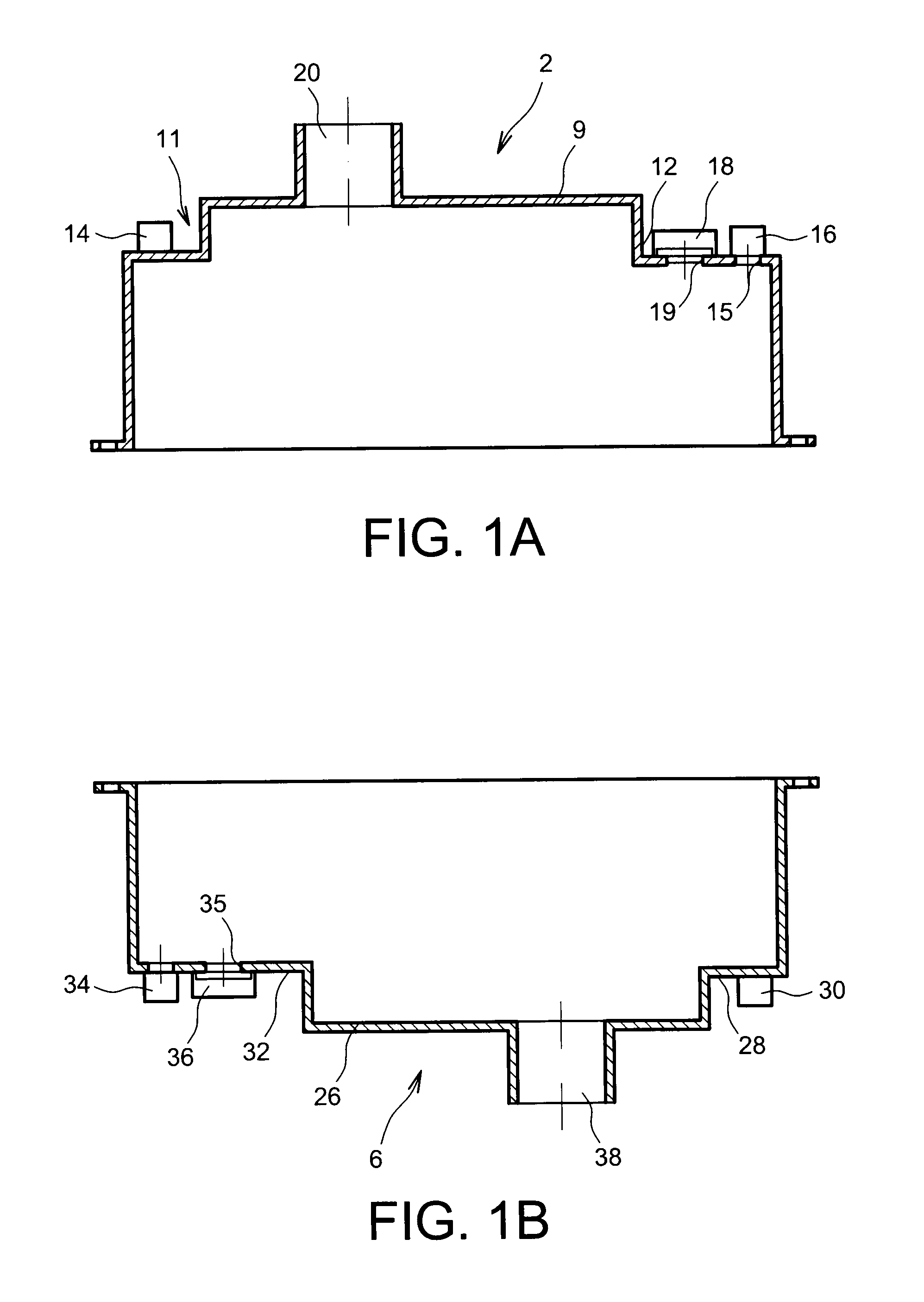
[0075]The enclosure may comprise an orifice for the supply of active fluid, provided on a side wall orthogonal to the electrolysis plates, which allows simplified design of the enclosure.

[0076]The enclosure comprises at least one orifice for the collection of the gas or gases generated at the cathodes on an upper wall of the enclosure, which improves the safety of the electrolyser.

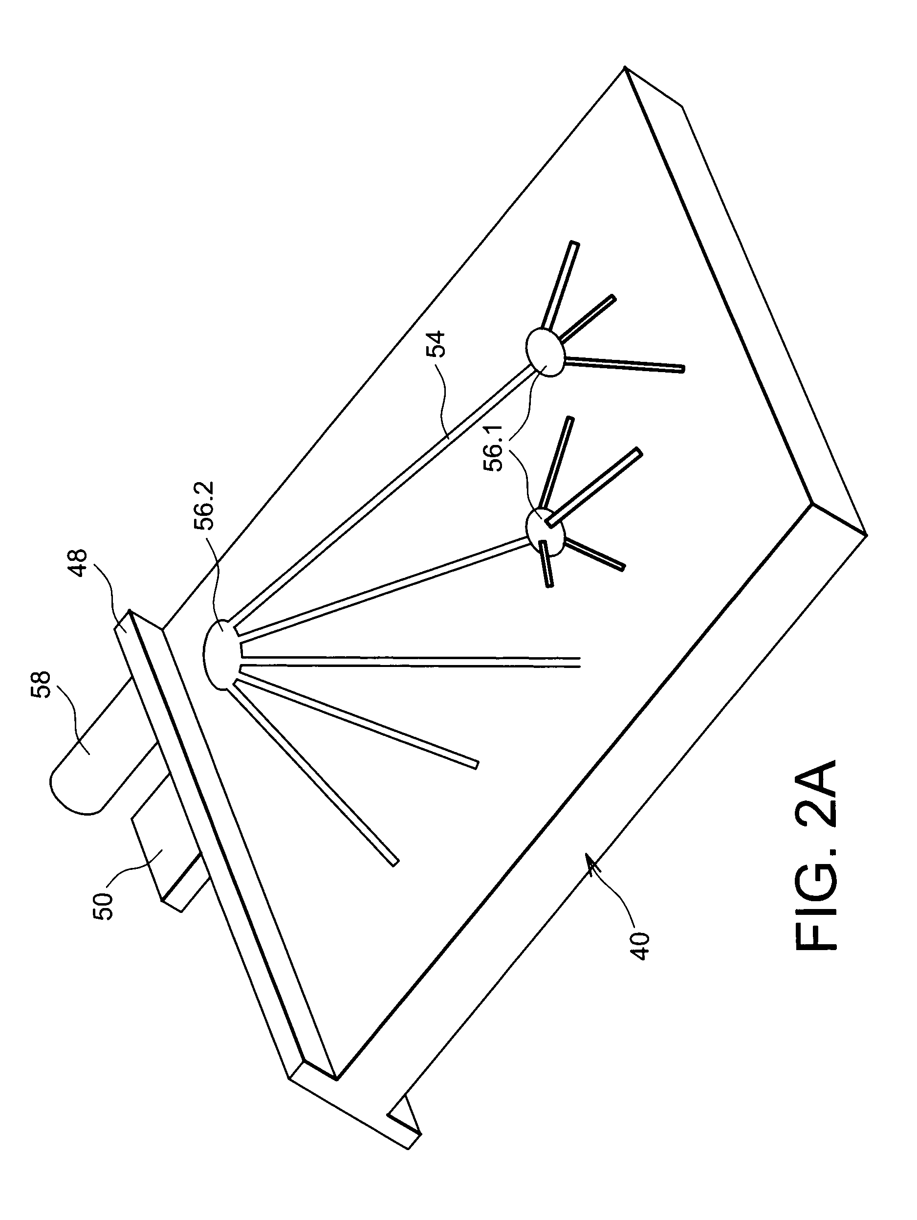
[0077]The electric connections between the different plates and with and an electricity supply source are advantageously provided on the outside of the enclosure. Further preferably, said electric connections are cooled. This improves conductivity.

[0078]A further subject of the present invention is an installation to produce gas ...


PUM

PropertyMeasurementUnit
operating temperatureaaaaaaaaaa
pressureaaaaaaaaaa
pressureaaaaaaaaaa

Abstract

An electrolyser for high-temperature electrolysis configured to operate in an allothermal mode, including an enclosure configured to maintain an electrolytic bath under high or very high pressure of several tens of bars, in which at least one electrolysis plate is arranged, and a heater internal to the enclosure. The electrolysis plate includes a plurality of electrolysis cells lying side by side in substantially one same plane, each electrolysis cell including an anode and a cathode. The heater uses a heat-carrier fluid.

Description

TECHNICAL AREA AND PRIOR ART[0001]The invention relates to high temperature endothermal electrolysis of about several hundred degrees Celsius, to decompose a reagent in liquid or vapour phase.[0002]The present invention relates more precisely to a high temperature, high pressure electrolyser operating in allothermal mode and offering stable, homogeneous operating conditions.[0003]In the remainder hereof, for clarity of the description, the example of water electrolysis will be used.[0004]When setting up current at the terminals of an electrolyser, part of the energy supplied by the direct current source is converted into heat inside the different conductors and electric contacts, but also during transfer of ions through the electrolyte. All these dissipative phenomena contribute towards useless loss of electric energy, current technological developments focusing both on the limiting of these phenomena and on the duration of stable functioning of electrolysers.[0005]Also, the energy ...

Claims


Application Information

Patent Timeline
Patent Type & Authority Patents(United States)
IPC IPC(8): C25B9/10C25B1/04C25B9/23
CPCC25B9/18C25B1/12C25B1/08Y02E60/366C25B9/00Y02E60/36C25B1/04C25B9/73C25B9/05C25B9/70
Inventor AUJOLLET, PATRICK
Owner COMMISSARIAT A LENERGIE ATOMIQUE ET AUX ENERGIES ALTERNATIVES
Why Eureka
Try Eureka