System for the detection and the depiction of objects in the path of marine vessels

a technology for depicting and detecting objects, applied in navigation instruments, steering initiations, instruments, etc., can solve the problems of high risk of accidents, increased consequences of collision with floating objects, and increased number of containers flushed overboard, so as to improve the depiction and accurate distance measurements

Active Publication Date: 2014-03-04
KONGSBERG DISCOVERY AS
View PDF7 Cites 19 Cited by
  • Summary
  • Abstract
  • Description
  • Claims
  • Application Information

AI Technical Summary

Benefits of technology

[0007]The main objective of the invention is to create a system for use on speed boats and other vessels to detect and issue a warning about drifting objects and other obstacles to navigation in the vessels course which solves the prior art problems described above. Moreover, it is an objective that the system is operable under all light conditions, both day and night, and provides a three dimensional depiction of objects upon and above the sea level within a certain sector, including accurate distance measurements to the objects. Moreover, it is an objective that the system provides an improved depiction at difficult visibility in fog and precipitation compared to light sensitive cameras and passive IR systems.
[0008]Finally, it is an objective that the system is arranged to stabilize the sweep area both in the horizontal and the vertical plane from the vessel's rolling and stamping movements, including short-lived deviations from controlled course (gearing), so that the vessel movements will not affect the quality of the system.
[0010]The system is operable under all light conditions, both day and night, and provides a three-dimensional depiction of objects upon and above the sea level within a certain sector, including measurements of the accurate distances to the objects. Moreover, the system can provide an improved depiction under difficult visibility in fog and precipitation compared to light sensitive cameras and passive IR systems.
[0011]Selection of laser wave length makes the system absolutely eye safe with regard to the prevailing Norwegian and international eye safety standard1, even when viewed through a binocular for marine use.
[0012]The system operates similar to traditional marine radars in that a laser beam pulse sweeps the field of view and detects the energy reflected passively from the surface. By using short pulses within the infrared wave length interval, we can obtain a resolution within the cm area both laterally and longitudinally (distance resolution). Contrary to traditional marine radar, the laser beam is swept both vertically and horizontally, resulting in a three-dimensional depiction, which makes it possible to detect wave height and height of objects relative to the sea level (for example bridge span etc.).
[0016]The sweeping unit preferably comprises two sweeping mechanisms, one that sweeps the laser beam in a vertical sector and illuminates a line on the sea level radial from the sweeping unit (line sweeper), and another that sweeps the line horizontally over the field of view in question (azimuth sweeper). The sweeping arrangement is constructed in a manner that it can stabilize the sweep against rolling and stamping movements including small course deviations to provide a stable picture of the environments. Moreover, the sweeping unit preferably comprises an optical sensor unit which detects the reflected laser pulses including fast analogous circuits based on the time difference between sent and reflected pulse, including pulse energy and pulse peak effect.

Problems solved by technology

Increasing vehicle and vessel speed in passenger transportation, car transportation and goods traffic has increased the consequences from collision with floating objects.
During recent years, the number of containers flushed overboard has increased significantly, and represents a high risk of accidents at sea in combination with drift timber and small leisure boats including certain whale species.
However, systems of this type are highly dependent on the light conditions and are not particularly useful when sailing at night in overcast weather.
This technique is based upon detection of small temperature differences between the object and the environments, and objects which have been in the sea for a long time may exhibit very small temperature difference and are therefore difficult to detect.
However, neither photosensitive camera nor IR systems are able to determine exact distances to objects within the view port.

Method used


Image

  • System for the detection and the depiction of objects in the path of marine vessels
  • System for the detection and the depiction of objects in the path of marine vessels
  • System for the detection and the depiction of objects in the path of marine vessels

Examples


Embodiment Construction

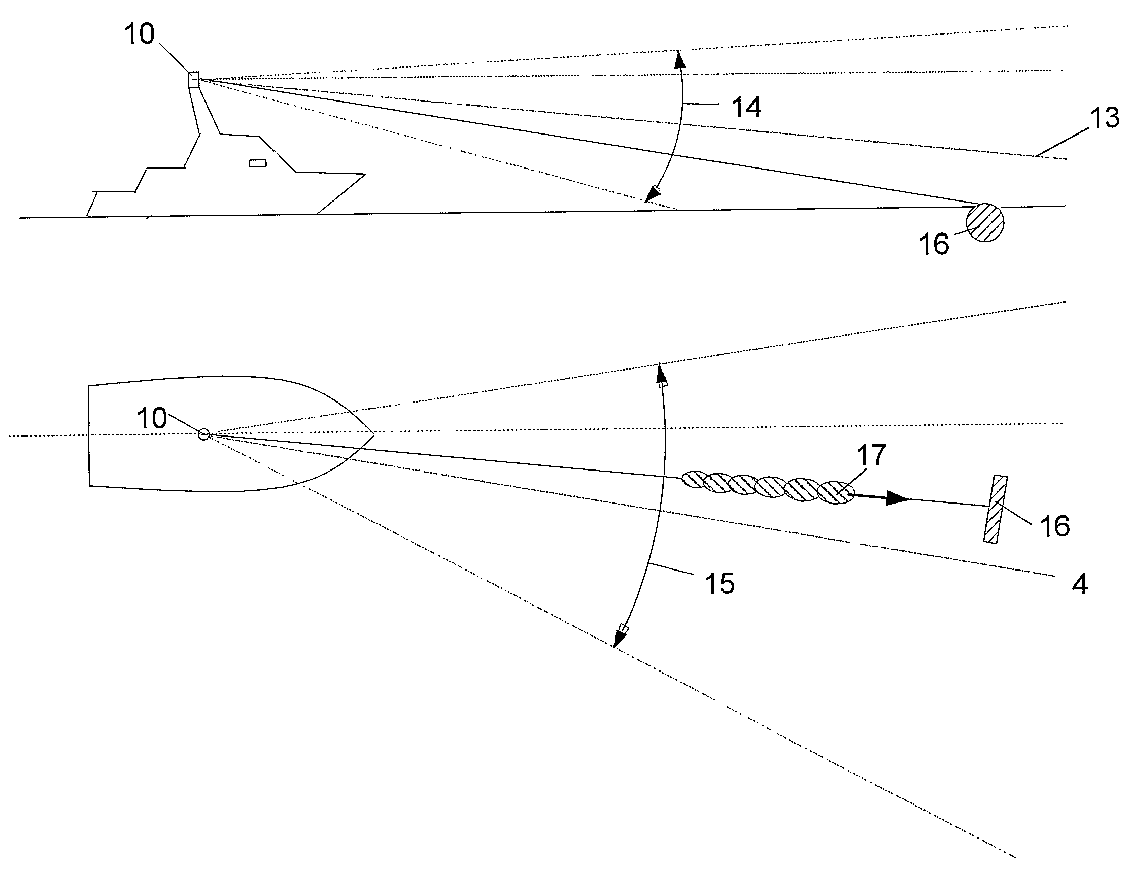
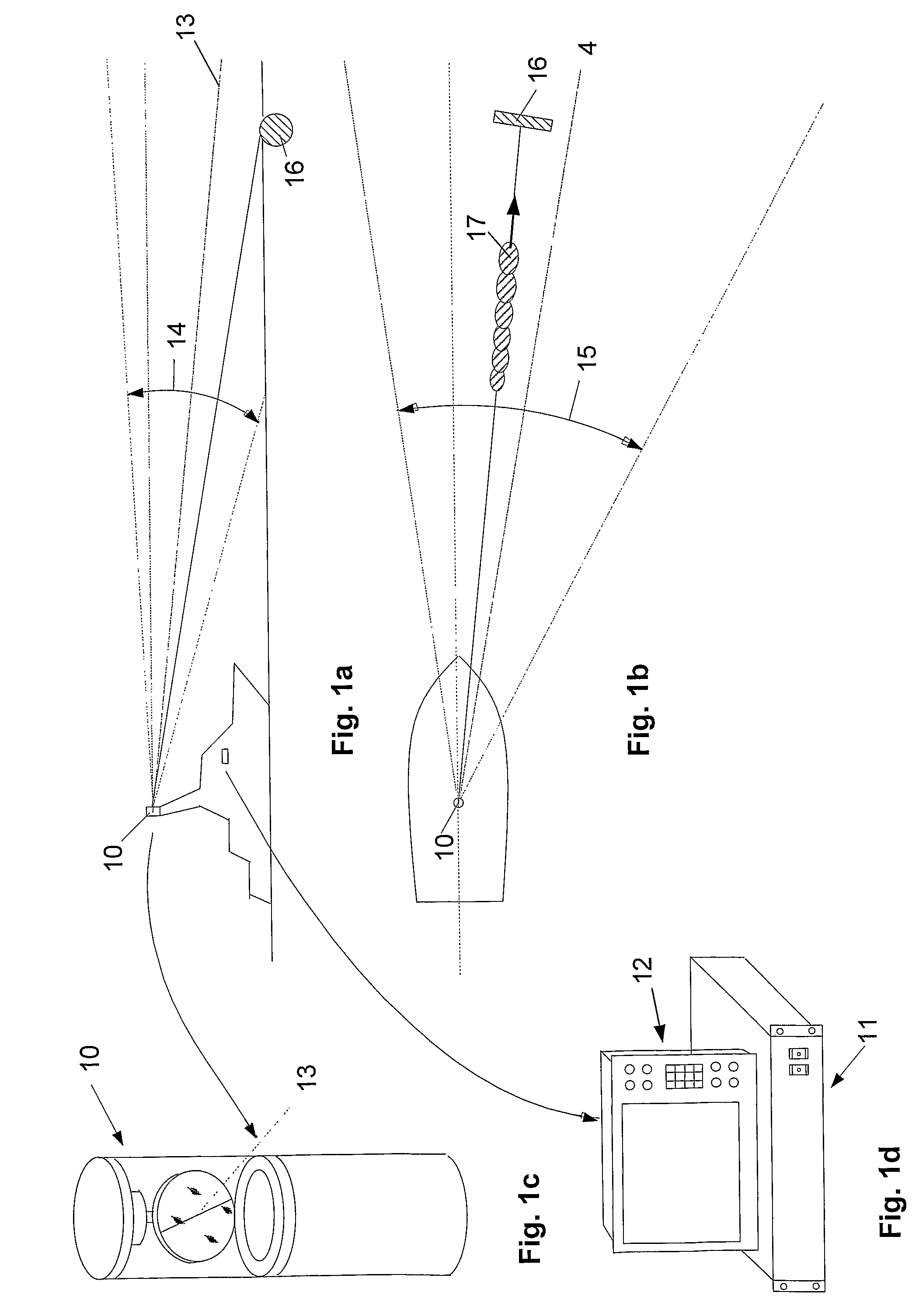
[0030]Firstly referring to FIGS. 1a and 1B, which illustrate a vessel provided with a system in accordance with the invention, hereinafter referred to as a marine laser-radar-system, abbreviated MLR system. The MLR system comprises a sweeping unit 10 (sweeping head) (shown enlarged in FIG. 1c), a control unit 11 and an operator panel (screen) 12 (shown in FIG. 1d). The sweeping unit 10 is arranged on a mast or to another platform above the wheel house roof to a vessel having best possible sight to the observation area. The control unit 11 is mounted within the wheel house to the vessel and integrated with existing power supply, navigation equipment, monitors and internal communication to show both video and radar pictures, and to notify about detected obstructions in a planned vessel course.

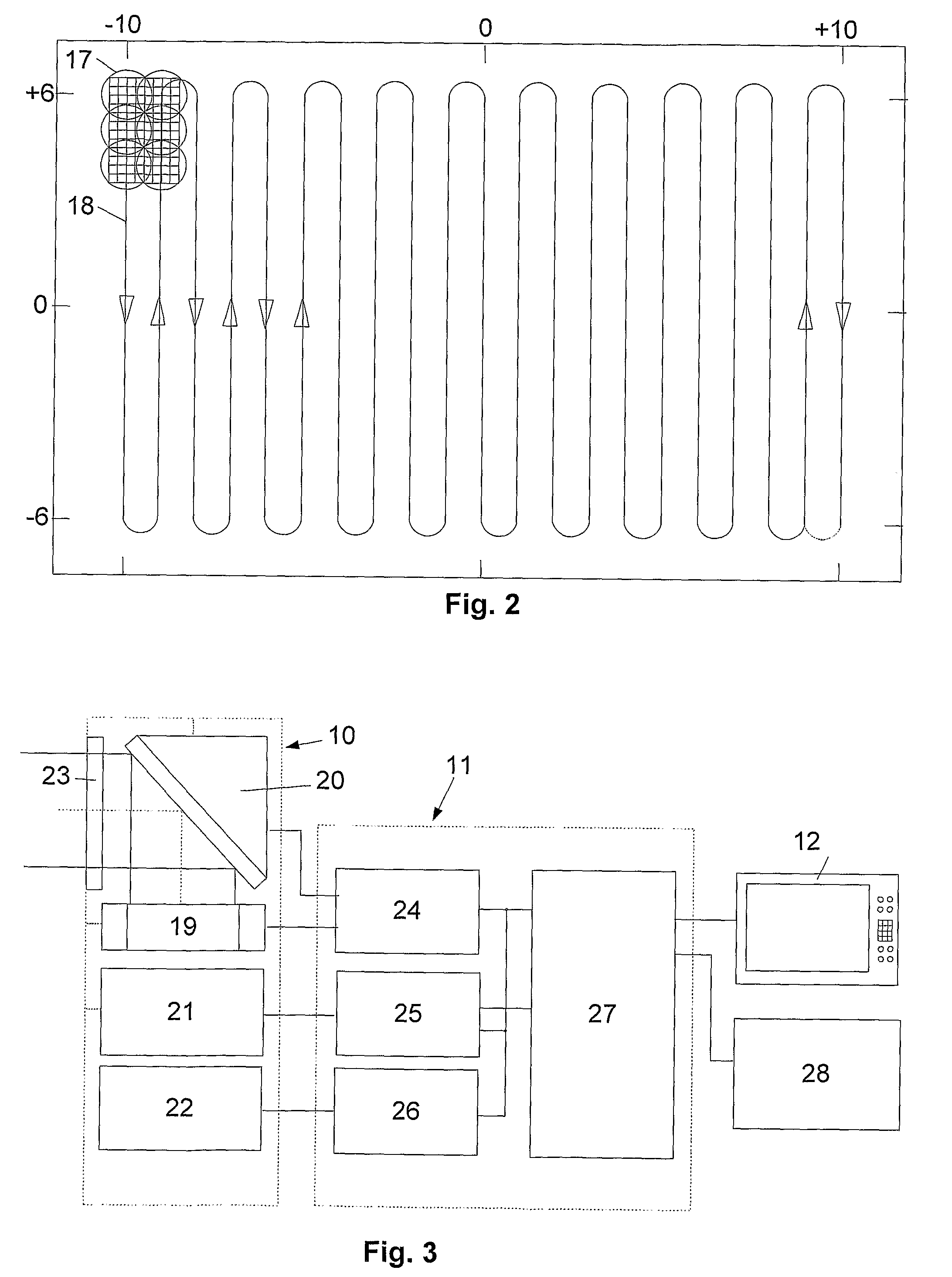
[0031]The MLR system can search a sector around a centre axis 13 by sweeping an infrared laser beam vertically within a vertical sector 14 and horizontally within a horizontal sector 15 or by a c...


PUM


Abstract

System for detection and depiction of objects in the path of marine vessels and for warning about objects that may constitute a risk to the navigational safety. The system includes a sweeping unit for illumination of objects within the field of view of the system, including a light source which emits a beam within the field of view of the system, an optical sensor and pulse processing unit including optical detectors for monitoring of the beam output power and generation of a start pulse for measurement of distance, for detection / reception of radiant energy reflected from objects, including measurement of distance to the reflecting object(s) based on the time delay between emitted and reflected light, including energy and peak effect of the pulses. The sweeping unit sweeps the beam and the optical detector's instantaneous field of view over the sweep area, by means of first and second sweeping mechanisms, to obtain directional information related to the instantaneous radiation direction relative to the vessel.

Description

BACKGROUND OF THE INVENTION[0001]The invention concerns a system for detection and depiction of objects in the path of speedboats and other marine vessels, including warning about objects that may constitute a danger to navigation safety.[0002]Increasing vehicle and vessel speed in passenger transportation, car transportation and goods traffic has increased the consequences from collision with floating objects. During recent years, the number of containers flushed overboard has increased significantly, and represents a high risk of accidents at sea in combination with drift timber and small leisure boats including certain whale species.[0003]U.S. Pat. No. 5,465,142 describes a sweeping laser-radar-system for detection of obstacles to helicopters and other aircrafts. The laser-radar-technology per se is described relatively detailed in “IR / EO Systems Handbook”, SPIE, 1992.[0004]Fast moving vessels are, in addition to radar, equipped with photosensitive video camera located as high as...

Claims


Application Information

Patent Timeline
Patent Type & Authority Patents(United States)
IPC IPC(8): G08G3/00G01S17/93G01S17/10G01S17/89
CPCG01S17/10G01S17/42G01S17/89G01S17/93
Inventor KLEPSVIK, JOHN O.
Owner KONGSBERG DISCOVERY AS
Why Eureka
Try Eureka