Low frequency inductive tagging for lifecycle management

a technology of lifecycle management and low frequency inductive tagging, which is applied in the field of detecting and tracking of animate and inanimate objects, can solve the problems of insufficient information about the functional significance of the differences outlined above, the range of devices is limited to a few inches, and the terminology used in the published literature is not well defined and can be confusing. , to achieve the effect of reducing the electromagnetic coupling of two co-planar air-core coils, reducing the electro-magnetic coup

Inactive Publication Date: 2014-03-25
VISIBLE ASSET INC
View PDF185 Cites 35 Cited by
  • Summary
  • Abstract
  • Description
  • Claims
  • Application Information

AI Technical Summary

Benefits of technology

[0051]As it turns out, however, there are many non-obvious and unexpected advantages in the use of low frequency, active radiating transceiver tags. They are especially useful for visibility and for tracking objects with large area loop antennas over other more expensive active radiating transponder HF UHF tags (e.g. Savi ST-654). These LF tags will function in harsh environments near water and steel and may have a full two-way digital communications protocol, digital static memory and optional processing ability, and can have sensors with memory and can have ranges of up to 100 feet. The active radiating transceiver tags can be far less costly than other active transceiver tags (many in the under-one-dollar range), and are often less costly than passive backscattered transponder RFID tags, especially those that require memory and make use of EEPROM. These low-frequency radiating transceiver tags also provide a high level of security since they have an on-board crystal than can provide a date-time stamp making full AES encryption and one-time-based pads possible. Finally, in most cases LF active radiant transponder tags have a battery life of 10-15 years using inexpensive CR2525 Li batteries with 3 million to 6 million transmissions.

Problems solved by technology

Much of the patent literature surrounding these radio tags and RFID tags as well as the published literature uses terminology that has not been well defined and can be confusing.
Many of the patents which are referenced below do not make many distinctions outlined in the above glossary and their authors may not at that time been fully informed about the functional significance of the differences outlined above.
This multifrequency approach limited data to about five bits to eight bits and the range of the devices was limited to only a few inches.
These two patents also teach that steel and other conductive metals may detune the antennas and degrade performance.
The ceramic filter required to increase the frequency from 50 kHz to a high frequency is, however, an expensive large external component, and phase-locked loops or other methods commonly used to multiply a frequency upward would consume considerable power.
This non-radiating mode reduces the power required to operate a tag and puts the detection burden on the base station.
HF and UHF tags are unable to use the carrier as a time base because the speed would require high speed chips and power consumption would be too high.
The major disadvantage of the prior art backscattered mode radio tag, is that it has limited power, limited range, and is susceptible to noise and reflections over a radiating active device.
As a result many backscattered tags do not work reliably in harsh environments and require a directional “line of sight” antenna.
However, since all of these tags use high frequencies the tags must continue to operate in backscattered mode to conserve battery life.
The power consumed by any electronic circuit tends to increase with the frequency of operation.
Because these tags are active backscattered transponders they cannot work in an on-demand peer-to-peer network setting, and they require line-of-sight antennas that provide a carrier that “illuminates” an area or zone or an array of carrier beacons.
These tags do provide full functionality and what might be called Real-Time Visibility, but they are expensive (over $100.00 US) and large (videotape size, 6¼ inch by 2⅛ inch by 1⅛ inch) because of the power issues described above and must use replaceable batteries since even with such a 1.5 inch by 6 inch Li battery these tags are only capable of 2,500 reads and writes.
An LF or ULF antenna cannot use either because the Q will be too low due to high resistance of the traces or silver paste.
Finally active radiating transceiver tags require large batteries, are expensive and may cost tens to hundreds of dollars.
One of the major disadvantages of a passive nonradiating system is that it requires the use of handheld readers or portals to read tags and changes in process control (e.g., U.S. Pat. No. 6,738,628: Electronic Physical Asset Tracking, 2004).
It will also be appreciated that the prior art has assumed low frequency tags to be slow, short range, and too costly.
Many of the commercial organizations recommending these higher frequencies believe that passive and active radio tags in these low frequencies are not suitable for any of these applications for reasons given above.
The transmission speed is inherently slow using ULF as compared to HF and UHF since the tag must communicate with low baud rates because of the low transmission carrier frequency.
Many sources of noise exist at these ULF frequencies from electronic devices, motors, fluorescent ballasts, computer systems, power cables.
Thus ULF is often thought to be inherently more susceptible to noise.
Radio tags in this frequency range are thought to be more expensive since they require a wound coil antenna because of the requirement for many turns to achieve optimal electrical properties (maximum Q).
In contrast HF and UHF tags can use antennas etched directly on a printed circuit board and ULF would have even more serious distance limitations with such an antenna.
Current networking methods used by high frequency tags, as used in HF and UHF, are impractical due to such low bandwidth of ULF tags described immediately above.

Method used


Image

  • Low frequency inductive tagging for lifecycle management
  • Low frequency inductive tagging for lifecycle management
  • Low frequency inductive tagging for lifecycle management

Examples


first embodiment

[0329]According to FIG. 40a, the tag energy source 66a comprises an energy storage device, such as a battery.

second embodiment

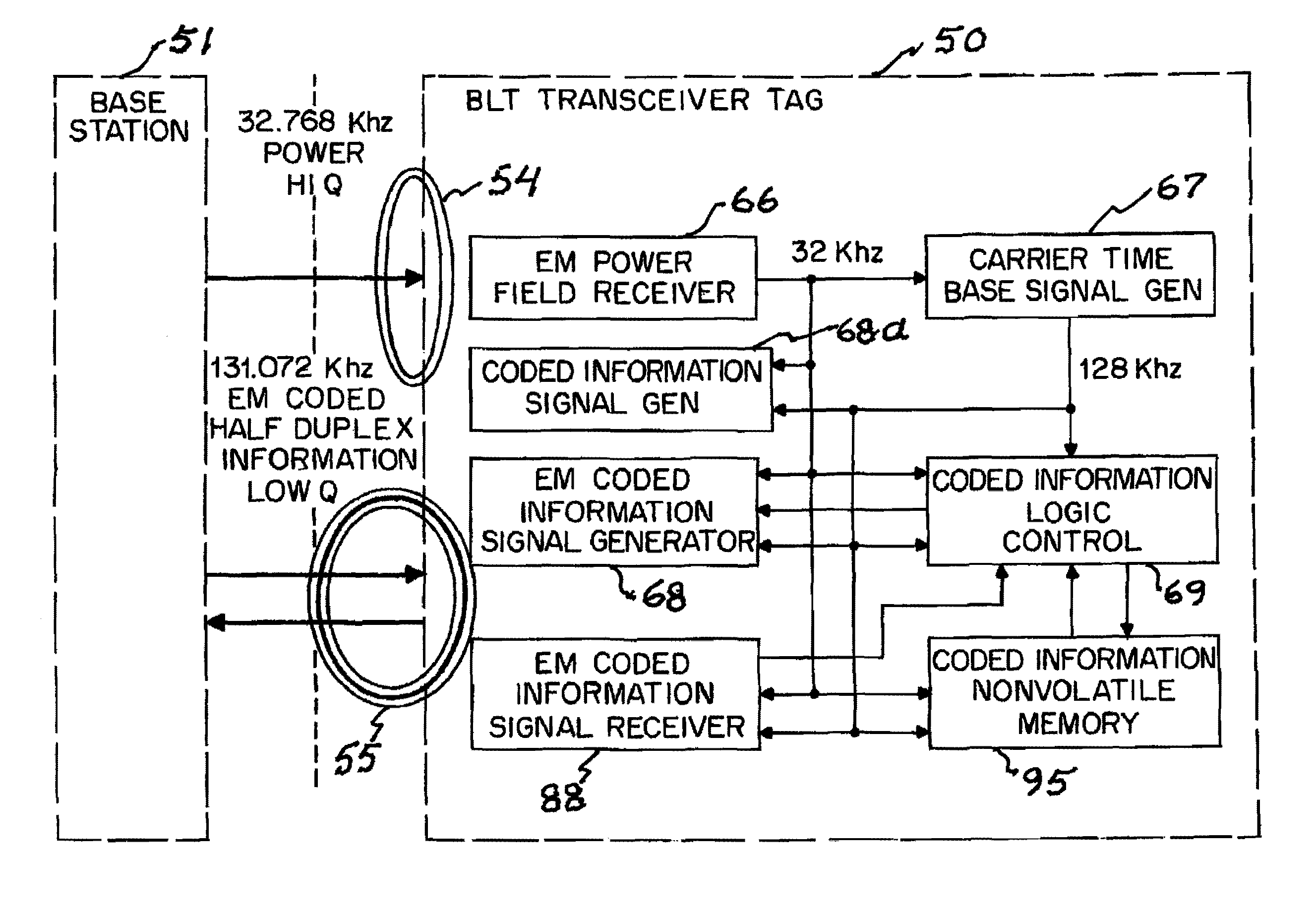
[0330]According to FIG. 40b, the tag antenna is a tag communication antenna 55 which preferably comprises a first elongated ferrite core for enhanced data communications. In this embodiment, the aforesaid tag energy source 66a comprises a tag power antenna 54 (preferably comprising a second elongated ferrite core, oriented substantially orthogonally to the first elongated ferrite core) operable to pick up electric energy induced by an applied varying electric field, and an energy storage device 66 / 67 (such as a capacitor or chargeable battery) connected to receive charging energy from the tag power antenna 54. Preferably, the tag communication antenna 55 is tuned to maximize signal strength at a frequency f(com) that is distinct from (e.g., is an integer multiple of) the frequency f(power) to which the tag power antenna 54 is tuned. Neither f(com) nor f(power) should exceed 1.0 megahertz. For example, when f(power)=64 Hz, then f(com) could be 128 Hz. According to this embodiment, re...


PUM


Abstract

A lifecycle management system for detection and tracking of drillpipes which carry low radio frequency tags that comprise an inductive antenna and transceiver operable at a first radio frequency below 1 megahertz, a transceiver operatively connected to that antenna, an ID data storage device, a microprocessor for handling data from the transceiver and data store, and a tag energization inductive antenna which can receive radio frequency energy from an ambient radio frequency field of a second low radio frequency. The system includes a field communication inductive antenna disposed, preferably at a distance of several feet from each object, that permits effective communication therewith at the aforesaid first radio frequency, a data receiver, transmitter and reader data processor in operative communication with the field communication inductive antenna, and a field energization inductive antenna which can produce the ambient radio frequency field at the tag energization inductive antenna.

Description

CROSS-REFERENCE TO RELATED APPLICATIONS[0001]The present application is a continuation-in-part of U.S. patent application Ser. No. 12 / 720,401 filed Mar. 9, 2010 and is also a continuation-in-part of U.S. patent application Ser. No. 12 / 848,772 filed Aug. 2, 2010, which is a continuation-in-part of U.S. patent application Ser. No. 12 / 719,352 filed Mar. 8, 2010. Both U.S. patent application Ser. No. 12 / 720,401 and U.S. patent application Ser. No. 12 / 719,352 are continuations-in-part of U.S. patent application Ser. No. 11 / 677,037 filed Feb. 20, 2007, now U.S. Pat. No. 7,675,422, which is a continuation-in-part of U.S. patent application Ser. No. 11 / 461,443 filed Jul. 31, 2006, now U.S. Pat. No. 7,277,014 (issued Oct. 2, 2007), which is a continuation-in-part of U.S. patent application Ser. No. 11 / 276,216 filed Feb. 17, 2006, now U.S. Pat. No. 7,164,359 (issued Jan. 16, 2007), which is a continuation of U.S. patent application Ser. No. 10 / 820,366 filed Apr. 8, 2004, now U.S. Pat. No. 7,0...

Claims


Application Information

Patent Timeline
Patent Type & Authority Patents(United States)
IPC IPC(8): G08B13/14
CPCG06Q10/08A01K11/008A01K15/023G06Q10/087G08B13/2414G07C9/00111G06Q50/02G06Q50/30G08B13/2471G07C2009/00793A01K11/004G07C9/28
Inventor AUGUST, M. JASONWATERHOUSE, PAULSTEVENS, JOHN K.
Owner VISIBLE ASSET INC
Why Eureka
Try Eureka